SMART I/O User’s Manual | Chapter 2 | |||
|
|
|
|
|
|
|
|
|
|
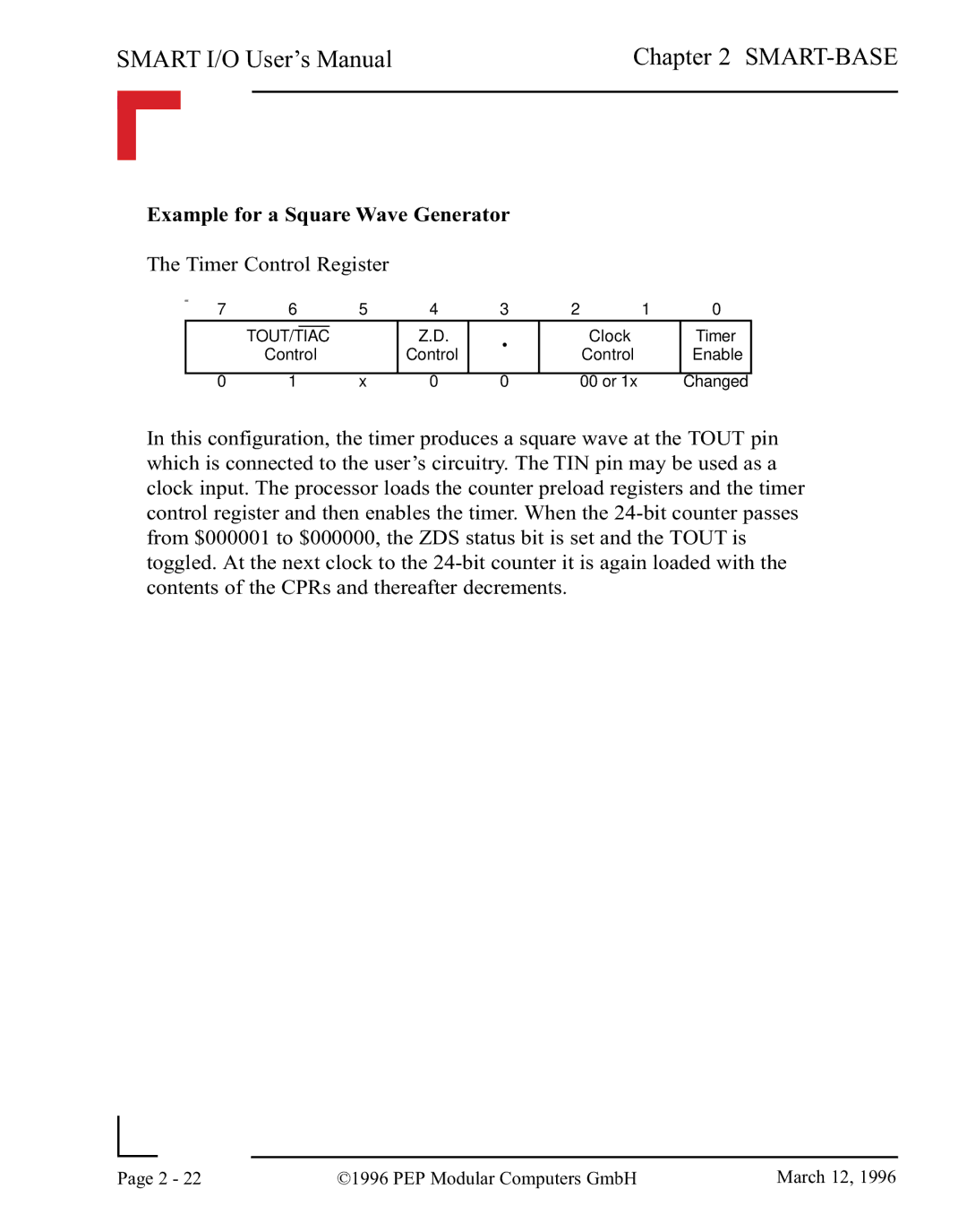
Example for a Square Wave Generator
The Timer Control Register
7 | 6 |
|
| 5 | 4 | 3 | 2 | 1 | 0 |
|
|
|
|
| Z.D. |
| Clock |
| Timer |
| TOUT/TIAC |
|
| • |
| ||||
| Control |
| Control | Control |
| Enable | |||
|
|
|
| ||||||
0 | 1 |
|
| x | 0 | 0 | 00 or 1x |
| Changed |
In this configuration, the timer produces a square wave at the TOUT pin which is connected to the user’s circuitry. The TIN pin may be used as a clock input. The processor loads the counter preload registers and the timer control register and then enables the timer. When the
|
|
|
|
Page | 2 - 22 | ©1996 PEP Modular Computers GmbH | March 12, 1996 |
|
|
|