Chapter 6 Communications Modules | SMART I/O User’s Manual | |||
|
|
|
|
|
|
|
|
|
|
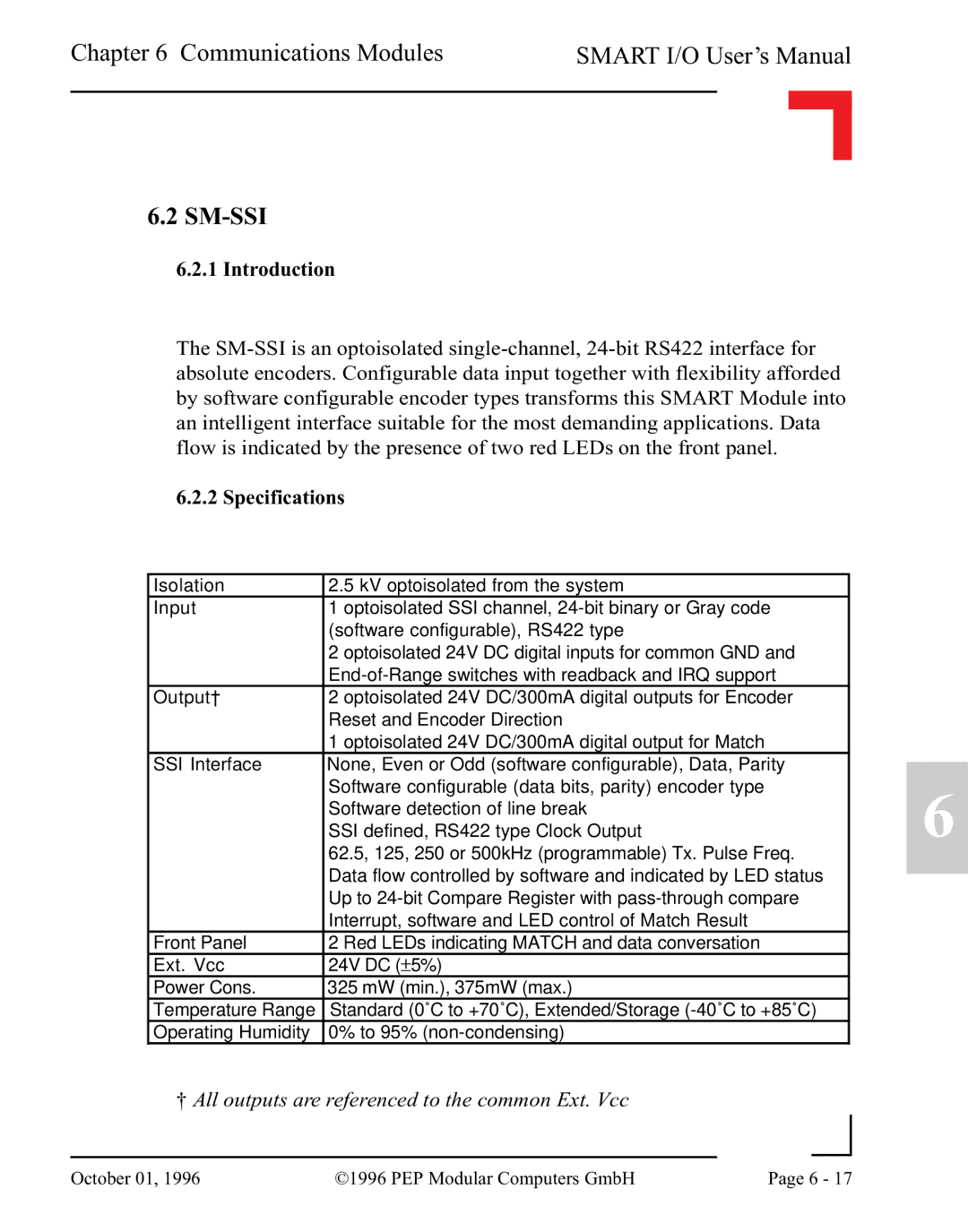
6.2SM-SSI
6.2.1Introduction
The
6.2.2 Specifications
Isolation | 2.5 kV optoisolated from the system |
Input | 1 optoisolated SSI channel, |
| (software configurable), RS422 type |
| 2 optoisolated 24V DC digital inputs for common GND and |
| |
Output† | 2 optoisolated 24V DC/300mA digital outputs for Encoder |
| Reset and Encoder Direction |
| 1 optoisolated 24V DC/300mA digital output for Match |
SSI Interface | None, Even or Odd (software configurable), Data, Parity |
| Software configurable (data bits, parity) encoder type |
| Software detection of line break |
| SSI defined, RS422 type Clock Output |
| 62.5, 125, 250 or 500kHz (programmable) Tx. Pulse Freq. |
| Data flow controlled by software and indicated by LED status |
| Up to |
| Interrupt, software and LED control of Match Result |
Front Panel | 2 Red LEDs indicating MATCH and data conversation |
Ext. Vcc | 24V DC (±5%) |
Power Cons. | 325 mW (min.), 375mW (max.) |
Temperature Range | Standard (0˚C to +70˚C), Extended/Storage |
Operating Humidity | 0% to 95% |
†All outputs are referenced to the common Ext. Vcc
6
|
|
|
|
October 01, 1996 | ©1996 PEP Modular Computers GmbH | Page 6 - 17 | |
|
| ||