SMART I/O User’s Manual | Chapter 2 | |||
|
|
|
|
|
|
|
|
|
|
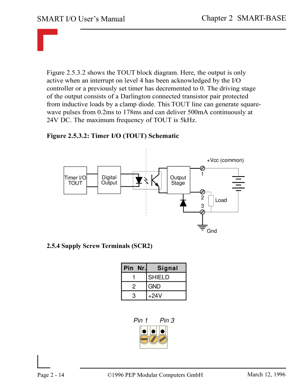
Figure 2.5.3.2 shows the TOUT block diagram. Here, the output is only active when an interrupt on level 4 has been acknowledged by the I/O controller or a previously set timer has decremented to 0. The driving stage of the output consists of a Darlington connected transistor pair protected from inductive loads by a clamp diode. This TOUT line can generate square- wave pulses from 0.2ms to 178ms and can deliver 500mA continuously at 24V DC. The maximum frequency of TOUT is 5kHz.
Figure 2.5.3.2: Timer I/O (TOUT) Schematic
Timer I/O | Digital | Output |
TOUT | Output | Stage |
2.5.4 Supply Screw Terminals (SCR2)
Pin Nr. Signal
1 SHIELD
2 GND
3 +24V
+Vcc (common)
1
2Load
Gnd
Pin 1 | Pin 3 | ||||||
|
|
|
|
|
|
|
|
|
|
|
|
|
|
|
|
|
|
|
|
Page | 2 - 14 | ©1996 PEP Modular Computers GmbH | March 12, 1996 |
|
|
|