SMART I/O User’s Manual | Chapter 2 | |||
|
|
|
|
|
|
|
|
|
|
The
Note
There is no internal line termination as laid down in DIN 19245 Part 1 and must be performed externally.
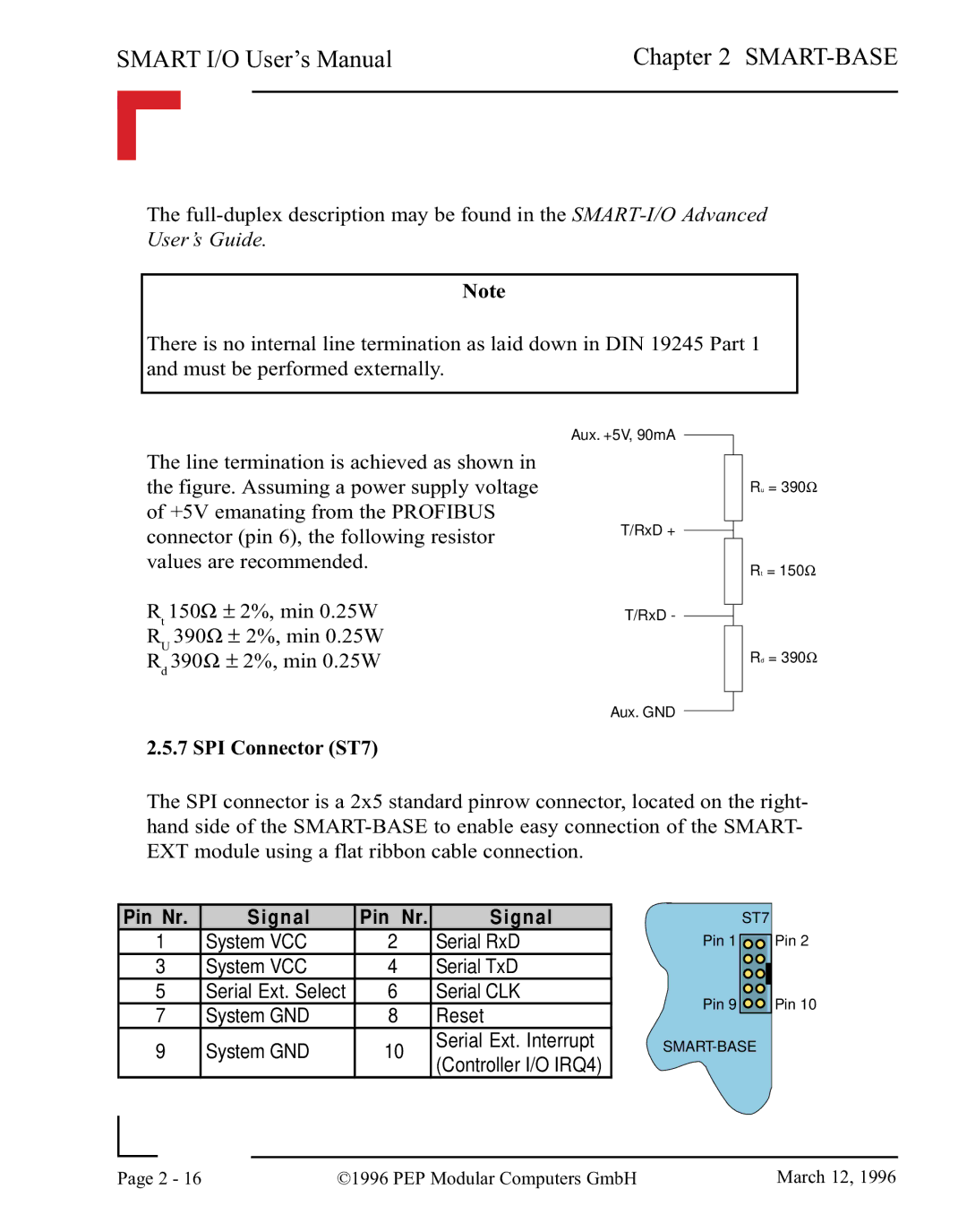
The line termination is achieved as shown in the figure. Assuming a power supply voltage of +5V emanating from the PROFIBUS connector (pin 6), the following resistor values are recommended.
Rt 150Ω ± 2%, min 0.25W RU 390Ω ± 2%, min 0.25W Rd 390Ω ± 2%, min 0.25W
Aux. +5V, 90mA
T/RxD +
T/RxD -
Ru = 390Ω
Rt = 150Ω
Rd = 390Ω
Aux. GND
2.5.7 SPI Connector (ST7)
The SPI connector is a 2x5 standard pinrow connector, located on the right- hand side of the
Pin Nr. | Signal | Pin Nr. | Signal | |
1 | System VCC | 2 | Serial RxD | |
3 | System VCC | 4 | Serial TxD | |
5 | Serial Ext. Select | 6 | Serial CLK | |
7 | System GND | 8 | Reset | |
9 | System GND | 10 | Serial Ext. Interrupt | |
(Controller I/O IRQ4) | ||||
|
|
|
ST7
Pin 1 ![]()
Pin 9 ![]()
![]()
Pin 2
Pin 10
|
|
|
|
Page | 2 - 16 | ©1996 PEP Modular Computers GmbH | March 12, 1996 |
|
|
|