Chapter 5 Analog Modules | SMART I/O User’s Manual | |||
|
|
|
|
|
|
|
|
|
|
5.3.5 Functional Description
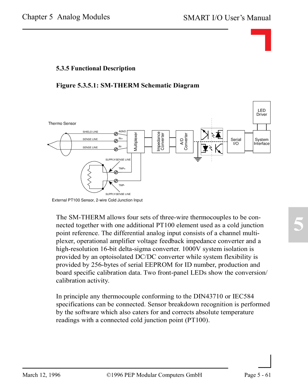
Figure 5.3.5.1: SM-THERM Schematic Diagram
LED
Driver
Thermo Sensor
SHIELD LINE | AGND | Multiplexer |
SENSE LINE | IN+ | |
SENSE LINE | IN- |
|
|
| |
| SUPPLY/SENSE LINE |
|
| TMP+ |
|
| TMP- |
|
| SUPPLY/SENSE LINE |
|
External PT100 Sensor,
Impedance | Converter |
A/D Converter
Serial
I/O
System
Interface
The
In principle any thermocouple conforming to the DIN43710 or IEC584 specifications can be connected. Sensor breakdown recognition is performed by the software which also caters for and corrects absolute temperature readings with a connected cold junction point (PT100).
5
|
|
|
|
March 12, 1996 | ©1996 PEP Modular Computers GmbH | Page 5 - 61 | |
|
| ||