SMART I/O User’s Manual | Chapter 4 Digital Modules | |||
|
|
|
|
|
|
|
|
|
|
4.1.7 Pinouts
Screw Terminal Pinouts
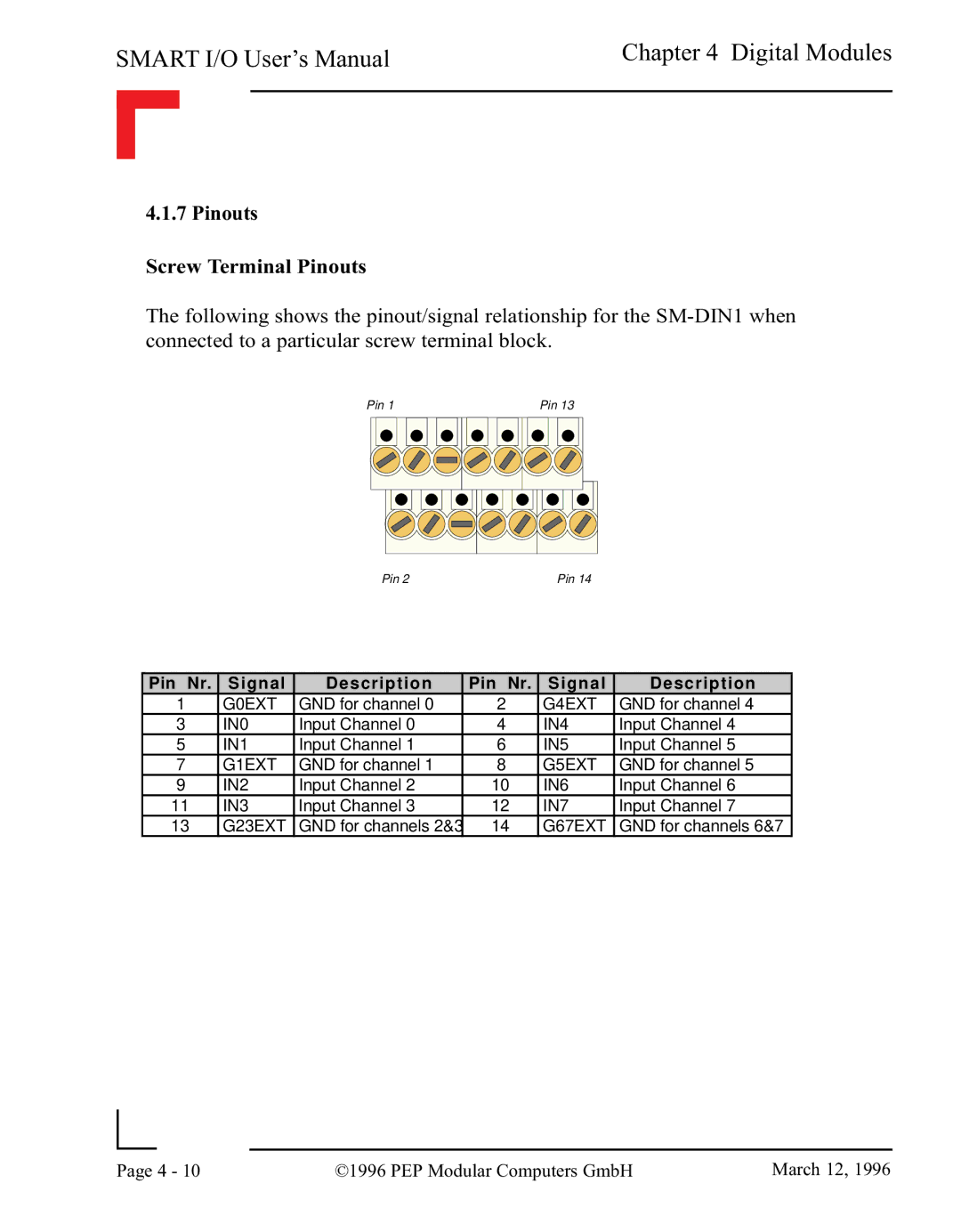
The following shows the pinout/signal relationship for the
Pin 1 | Pin 13 |
Pin 2 | Pin 14 |
Pin Nr. | Signal | Description | Pin Nr. | Signal | Description |
1 | G0EXT | GND for channel 0 | 2 | G4EXT | GND for channel 4 |
3 | IN0 | Input Channel 0 | 4 | IN4 | Input Channel 4 |
5 | IN1 | Input Channel 1 | 6 | IN5 | Input Channel 5 |
7 | G1EXT | GND for channel 1 | 8 | G5EXT | GND for channel 5 |
9 | IN2 | Input Channel 2 | 10 | IN6 | Input Channel 6 |
11 | IN3 | Input Channel 3 | 12 | IN7 | Input Channel 7 |
13 | G23EXT | GND for channels 2&3 | 14 | G67EXT | GND for channels 6&7 |
|
|
|
|
Page | 4 - 10 | ©1996 PEP Modular Computers GmbH | March 12, 1996 |
|
|
|