Chapter 4 Digital Modules | SMART I/O User’s Manual | ||||
|
|
|
|
|
|
|
|
|
|
|
|
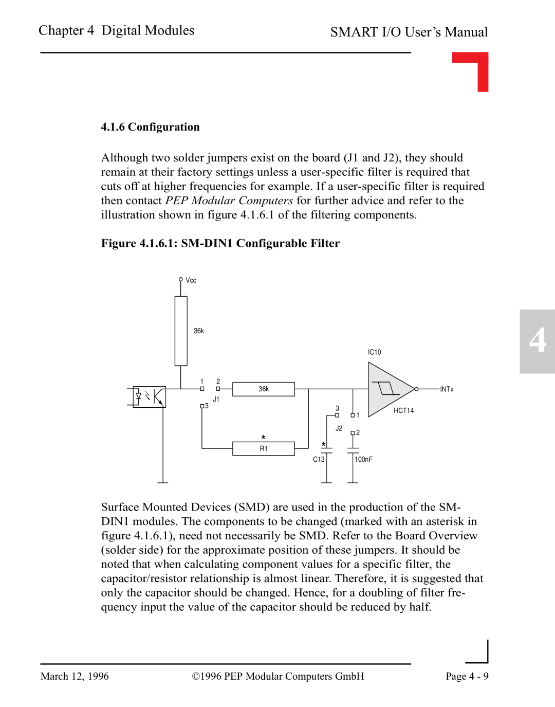
4.1.6 Configuration
Although two solder jumpers exist on the board (J1 and J2), they should remain at their factory settings unless a
Figure 4.1.6.1: SM-DIN1 Configurable Filter
![]() Vcc
Vcc
36k
IC10
4
1 2
J1
![]() 3
3
36k
*
R1
*
C13
INTx
| 3 |
| 1 | HCT14 | ||||
|
|
|
|
| ||||
| J2 |
|
| 2 |
| |||
|
|
|
|
|
|
|
|
|
|
|
|
|
|
|
|
|
|
|
|
|
|
|
| 100nF |
| |
|
|
|
|
|
|
|
|
|
Surface Mounted Devices (SMD) are used in the production of the SM- DIN1 modules. The components to be changed (marked with an asterisk in figure 4.1.6.1), need not necessarily be SMD. Refer to the Board Overview (solder side) for the approximate position of these jumpers. It should be noted that when calculating component values for a specific filter, the capacitor/resistor relationship is almost linear. Therefore, it is suggested that only the capacitor should be changed. Hence, for a doubling of filter fre- quency input the value of the capacitor should be reduced by half.
|
|
|
|
March 12, 1996 | ©1996 PEP Modular Computers GmbH | Page 4 - 9 | |
|
| ||