SMART I/O User’s Manual | Chapter 2 | |||
|
|
|
|
|
|
|
|
|
|
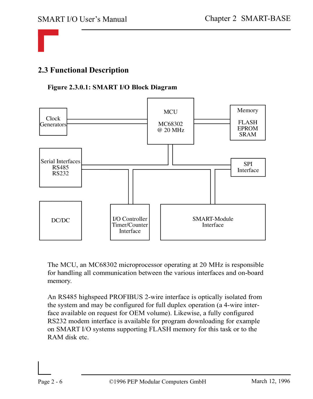
2.3 Functional Description
Figure 2.3.0.1: SMART I/O Block Diagram
|
|
|
|
|
|
|
|
|
| MCU |
| Memory | |
Clock |
|
|
| |||
|
| MC68302 |
| FLASH |
| |
Generators |
|
|
|
| ||
| ||||||
|
|
| @ 20 MHz |
| EPROM | |
|
|
|
|
| SRAM | |
|
|
|
|
| ||
|
|
|
|
|
|
|
|
|
|
|
|
|
|
|
|
|
|
|
| |
Serial Interfaces |
|
|
|
|
| |
|
| SPI | ||||
RS485 |
|
|
| |||
|
|
| Interface | |||
RS232 |
|
|
| |||
|
|
|
|
| ||
|
|
|
|
|
|
|
DC/DC
I/O Controller
Timer/Counter
Interface
Interface
The MCU, an MC68302 microprocessor operating at 20 MHz is responsible for handling all communication between the various interfaces and
An RS485 highspeed PROFIBUS
|
|
|
|
Page | 2 - 6 | ©1996 PEP Modular Computers GmbH | March 12, 1996 |
|
|
|
