Digital Modules | SMART I/O User’s Manual | |||
|
|
|
|
|
|
|
|
|
|
|
|
|
|
|
3) for the approximate position of the jumpers. Notice should be taken of the fact, that when calculating component values for a specific filter, the capacitor/resistor relationship is almost linear. For this purpose, it is suggested that only the capacitor be changed. Hence, for a doubling of the filter frequency input, the value of the capacitor should be reduced by half.
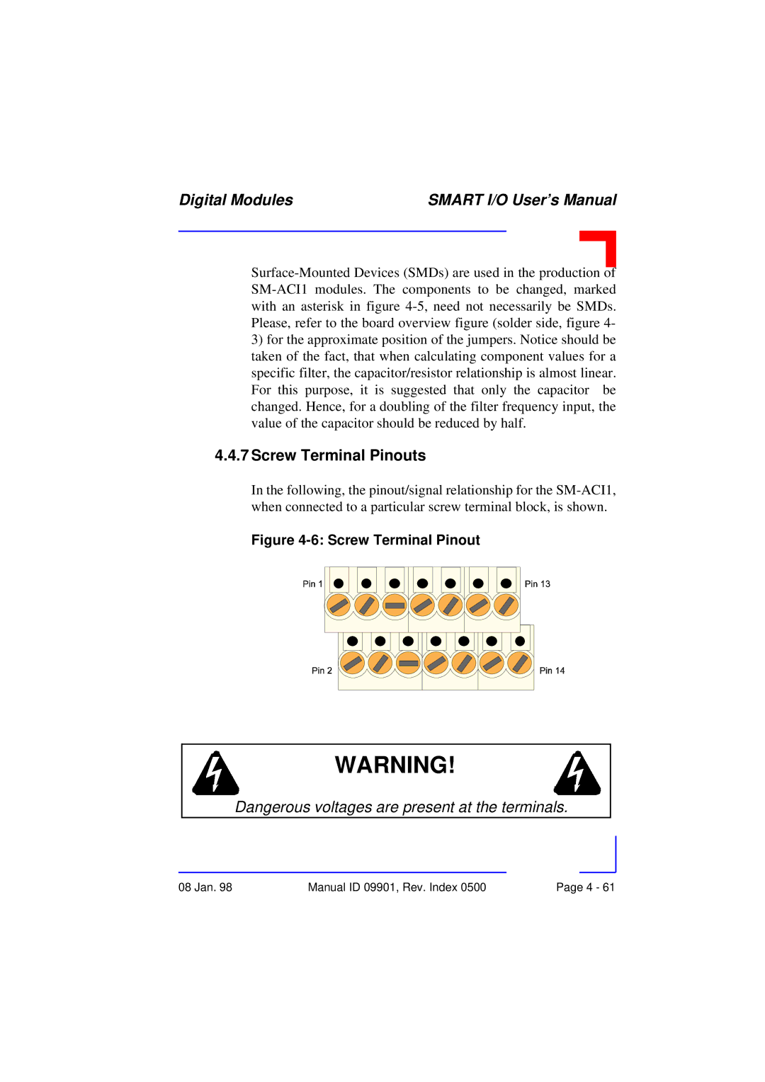
4.4.7Screw Terminal Pinouts
In the following, the pinout/signal relationship for the
Figure 4-6: Screw Terminal Pinout
WARNING!
Dangerous voltages are present at the terminals.
08 Jan. 98 | Manual ID 09901, Rev. Index 0500 | Page 4 - 61 |