Introduction (cont.)
Operation in "ECO" mode
Normal operation
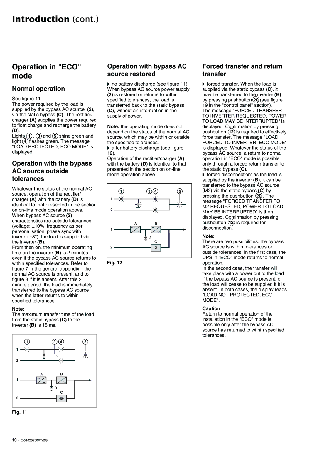
See figure 11.
The power required by the load is supplied by the bypass AC source (2), via the static bypass (C). The rectifier/ charger (A) supplies the power required to float charge and recharge the battery
(D).
Lights 1 , 3 and 5 shine green and light 4 flashes green. The message "LOAD PROTECTED, ECO MODE" is displayed.
Operation with the bypass AC source outside tolerances
Whatever the status of the normal AC source, operation of the rectifier/ charger (A) with the battery (D) is identical to that presented in the section on
From then on, the minimum operating time on the inverter (B) is 2 minutes even if the bypass AC source returns to within specified tolerances. Refer to figure 7 in the general appendix if the normal AC source is present, and to figure 8 if it is absent. After this 2 minute period, the load is immediately transferred to the bypass AC source when the latter returns to within specified tolerances.
Note:
The maximum transfer time of the load from the static bypass (C) to the inverter (B) is 15 ms.
1 | 3 | 4 | 5 |
1 |
|
|
|
2 |
|
|
|
A |
| B |
|
1 |
|
|
|
| D |
|
|
|
| C |
|
2 |
|
|
|
Fig. 11
Operation with bypass AC source restored
◗no battery discharge (see figure 11). When bypass AC source power supply
(2) is restored or returns to within specified tolerances, the load is transferred back to the static bypass
(C), without an interruption in the supply of power.
Note: this operating mode does not depend on the status of the normal AC source, which may be within or outside the specified tolerances.
◗after battery discharge (see figure 12).
Operation of the rectifier/charger (A) with the battery (D) is identical to that presented in the section on
1 | 3 | 4 | 5 |
1 |
|
|
|
2 |
|
|
|
A |
| B |
|
1 |
|
|
|
| D |
|
|
|
| C |
|
2 |
|
|
|
Fig. 12
Forced transfer and return transfer
◗forced transfer. When the load is supplied via the static bypass (C), it may be transferred to the inverter (B) by pressing pushbutton 20 (see figure 19 in the "control panel" section). The message "FORCED TRANSFER TO INVERTER REQUESTED, POWER TO LOAD MAY BE INTERRUPTED" is displayed. Confirmation by pressing pushbutton 12 is required to effectively force transfer. The message "LOAD
FORCED TO INVERTER, ECO MODE" is displayed. Whatever the status of the bypass AC source, a return to normal operation in "ECO" mode is possible only through a forced return transfer to the static bypass (C).
◗forced disconnection: as the load is supplied by the inverter (B), it can be transferred to the bypass AC source (M2) via the static bypass (C) by pressing the pushbutton 20 . The message "FORCED TRANSFER TO M2 REQUESTED, POWER TO LOAD MAY BE INTERRUPTED" is then displayed. Confirmation by pressing pushbutton 12 is required for disconnection.
Note:
There are two possibilities: the bypass AC source is within tolerances or outside tolerances. In the first case, the UPS in "ECO" mode returns to normal operation.
In the second case, the transfer will take place with a power cut to the load if the bypass AC source is present, or the load will cease to be supplied if it is absent. In both cases, the display reads
"LOAD NOT PROTECTED, ECO MODE".
Caution:
Return to normal operation of the installation in the "ECO" mode is possible only after the bypass AC source has returned to within specified tolerances.
