Control-panel display
General organisation | Display of messages |
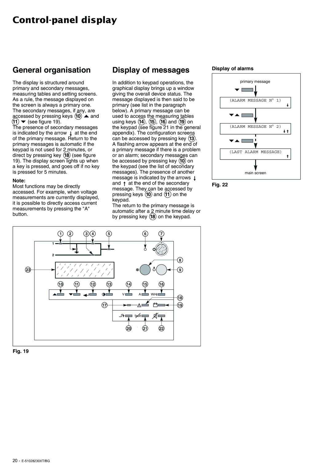
Display of alarms
The display is structured around primary and secondary messages, measuring tables and setting screens. As a rule, the message displayed on the screen is always a primary one. The secondary messages, if any, are accessed by pressing keys 10 ![]() and
and
11 (see figure 19).
The presence of secondary messages is indicated by the arrow at the end of the primary message. Return to the primary messages is automatic if the keypad is not used for 2 minutes, or direct by pressing key 18 (see figure 19). The display screen lights up when a key is pressed, and goes off if no key is pressed for 5 minutes.
Note:
Most functions may be directly accessed. For example, when voltage measurements are currently displayed, it is possible to directly access current measurements by pressing the "A" button.
In addition to keypad operations, the graphical display brings up a window giving the overall device status. The message displayed is then said to be primary (see list in the paragraph below). A primary message can be used to access the measuring tables using keys 14 , 15 , 16 and 19 on the keypad (see figure 21 in the general appendix). The configuration screens can be accessed by pressing key 13 . A flashing arrow appears at the end of a primary message if there is a problem or an alarm; secondary messages can be accessed by pressing key 10 on the keypad (see the list of secondary messages). The presence of another message is indicated by the arrows and ![]() at the end of the secondary message. They can be accessed by pressing keys 10 and 11 on the keypad.
at the end of the secondary message. They can be accessed by pressing keys 10 and 11 on the keypad.
The return to the primary message is automatic after a 2 minute time delay or by pressing key 18 on the keypad.
primary message |
| |
(ALARM | MESSAGE N° | 1) |
(ALARM | MESSAGE N° | 2) |
(LAST ALARM MESSAGE) | ||
main screen |
| |
Fig. 22
1 | 2 | 3 | 4 | 5 |
| 6 | 7 |
1 |
|
|
|
|
|
|
|
2 |
|
|
|
|
|
|
|
|
|
|
|
|
|
| 8 |
23 |
|
|
|
|
|
| 9 |
10 | 11 |
| 12 | 13 | 14 | 15 | 16 |
|
|
|
|
| V | A | W.Hz |
|
|
|
|
|
|
| 18 |
|
|
|
| 17 |
|
| 19 |
|
|
|
|
|
| fault |
|
|
|
|
|
| 20 | 21 | 22 |
Fig. 19