Introduction (cont.)
Different types of MGE™ Galaxy™ PW systems
A | B |
1 |
|
| D |
| C |
2 |
|
Fig. 2
A | B |
1 |
|
| D |
Fig. 3
Frequency converter without battery backup power
Parallel UPS system
A | B |
1 |
|
2 | D |
| |
| C |
A | B |
1 |
|
2 | D |
| |
| C |
Fig. 5
See figure 5 showing two parallel- connected (redundant) UPS units. A static bypass (C) does not exist in
configurations.
When increased power is required (two to four parallel units), an external bypass must be added (see figure 6).
Isolation and protection devices
(See figure 1 on previous page):
◗ | Q1 (switch): |
◗ | isolation of the rectifier/charger (A) |
from the normal AC source (1); | |
◗ | rectifier/charger (A) |
◗ | QF1 (circuit breaker): |
◗ | battery (D) protection and isolation; |
◗ | Q5N (switch): |
◗ | isolation of the UPS (B) from the |
load; | |
◗ | Q4S (switch): |
◗ isolation of the static bypass (C) from | |
the bypass AC source (2); | |
◗ | Q3BP (switch): |
◗ | bypass switch for maintenance; |
◗ | FUE (fuses): |
◗ | protection of the rectifier/charger (A) |
from the normal AC source; | |
◗ | FUS (fuses): |
◗ | protection of the inverter (B) from the |
Frequency converter with battery backup power
A | B |
1 | 2 |
Fig. 4
1 |
|
|
|
|
|
|
|
|
| |
|
|
|
|
|
|
|
|
| ||
|
|
|
|
|
|
|
|
| ||
Q4S 2 |
|
|
|
|
|
|
|
| ||
Galaxy 1 |
|
|
|
|
| |||||
|
|
|
|
| ||||||
| 1 |
|
|
|
|
|
| |||
|
|
|
|
|
|
| ||||
|
|
|
|
|
|
|
|
|
| |
|
|
|
|
|
|
|
|
|
| |
|
|
|
|
|
|
|
| |||
| 2 |
| Galaxy 2 |
|
|
| ||||
1 |
|
|
|
| ||||||
|
|
|
|
|
|
|
|
| ||
|
|
|
|
|
|
|
|
| ||
|
|
|
|
|
|
|
| |||
2 |
| Galaxy 3 |
|
|
| |||||
1 |
|
|
|
|
|
|
|
|
| |
|
|
|
|
|
|
|
|
| ||
|
|
|
|
|
|
|
| |||
2 |
| Galaxy 4 |
|
|
| |||||
|
|
|
|
|
|
|
|
|
|
|
Q3BP
Q5N
load. |
Note:
◗switch Q3BP does not exist on parallel UPS systems constituted to increase available power;
◗the "Q3BP" and "Q4S" switches do not exist on frequency converters;
◗circuit breaker QF1 does not exist on installations without batteries.
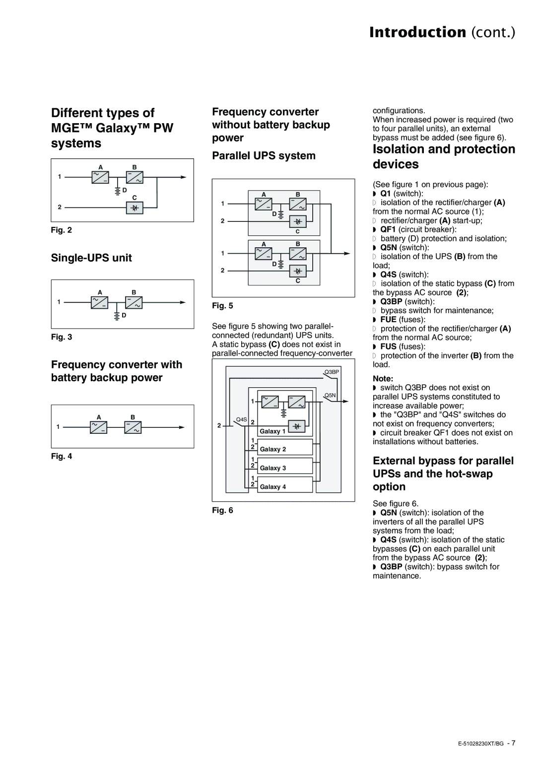
External bypass for parallel UPSs and the hot-swap option
See figure 6.
Fig. 6
◗Q5N (switch): isolation of the inverters of all the parallel UPS systems from the load;
◗Q4S (switch): isolation of the static bypasses (C) on each parallel unit from the bypass AC source (2);
◗Q3BP (switch): bypass switch for maintenance.