Maintenance
Maintenance configuration
Single-UPS unit or UPS in "ECO" mode
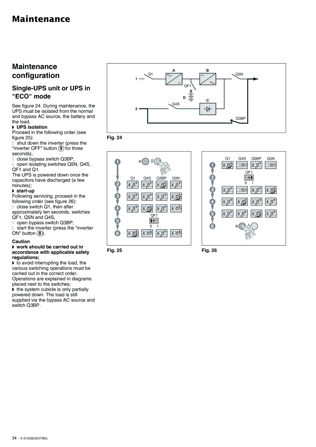
See figure 24. During maintenance, the UPS must be isolated from the normal and bypass AC source, the battery and the load.
◗UPS isolation
Q1
1
2
A
QF1
D
Q4S
B
Q5N
C
Q3BP
Proceed in the following order (see figure 25):
◗ shut down the inverter (press the |
"inverter OFF" button 9 for three |
seconds), |
◗ close bypass switch Q3BP, |
Fig. 24
Q1
Q4S Q3BP
Q5N
◗ open isolating switches Q5N, Q4S, |
QF1 and Q1. |
The UPS is powered down once the |
capacitors have discharged (a few |
1
Q1
Q4S
Q3BP
Q5N
1
2
0
1
OFF | 0 | 1 |
|
QF1
OFF![]()
minutes); |
◗ |
2
0
1
0
1
0
1
0
1
3
0
1
OFF | 0 | 1 |
|
|
0
1
Following servicing, proceed in the following order (see figure 26):
3
0
1
0
1
0
1
0
1
4
0
1
0 | 1 | 0 | 1 |
|
|
0
1
◗ close switch Q1, then after |
4
0
1
0
1
0
1
0
1
approximately ten seconds, switches | |
QF1, Q5N and Q4S, | |
◗ | open bypass switch Q3BP, |
◗ | start the inverter (press the "inverter |
ON" button 8 ). | |
Caution
QF1 | |
5 |
|
0 | I |
6 | 0 | 1 | 0 | 1 | 0 | 1 | 0 | 1 |
|
|
|
|
5
6
0
1
0 | 1 | 0 | 1 |
|
|
0
1
◗work should be carried out in accordance with applicable safety regulations;
◗to avoid interrupting the load, the various switching operations must be carried out in the correct order. Operations are explained in diagrams placed next to the switches;
◗the system cubicle is only partially powered down. The load is still supplied via the bypass AC source and switch Q3BP.
Fig. 25 | Fig. 26 |