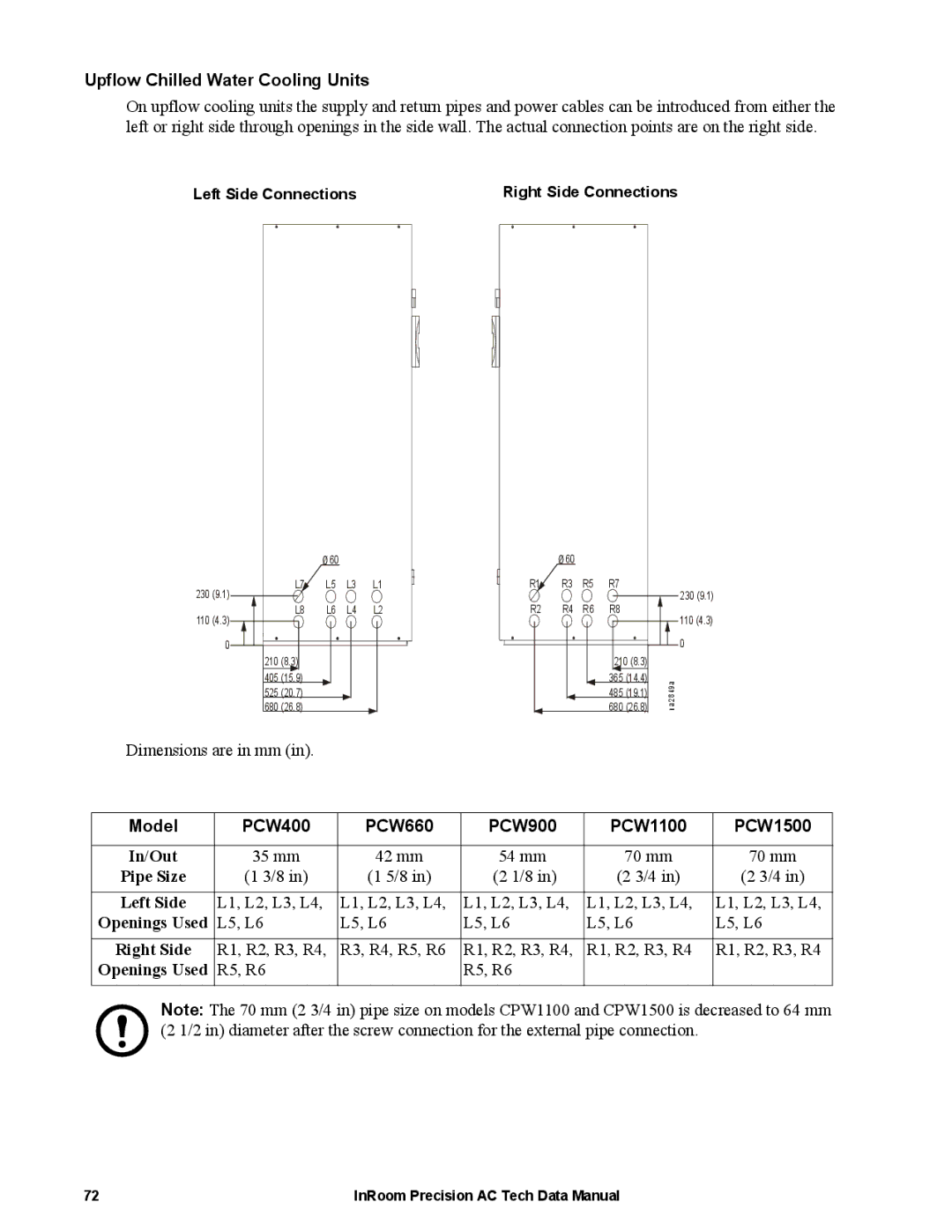
ACPCW40-150, ACPDX21-86 specifications
The APC ACPCW40-150 and APCDX21-86 are two innovative products from APC (American Power Conversion), known for their commitment to providing reliable power solutions for various applications. These models are tailored to meet the demands of modern businesses by focusing on efficiency, safety, and advanced technology.The APC ACPCW40-150 is a 1500 VA line-interactive UPS (Uninterruptible Power Supply) system designed for protecting sensitive electronic equipment. This model features Automatic Voltage Regulation (AVR) which ensures consistent output voltage by correcting minor voltage fluctuations without switching to battery power. This capability extends battery life and enhances overall system reliability. The ACPCW40-150 is equipped with a user-friendly LCD interface providing real-time information on battery status, load capacity, and various operational parameters, making monitoring straightforward.
The ACPCW40-150 utilizes sine wave output to ensure compatibility with a broad range of devices, from servers to networking equipment. Its compact design makes it suitable for limited spaces, while multiple outlets allow for easy connection of various devices. The intelligent battery management system further optimizes charging cycles and enhances battery longevity, essential for organizations aiming to minimize downtime and maintenance costs.
On the other hand, the APCDX21-86 is a high-performance surge protector designed to safeguard electronic devices from power surges and spikes. This model boasts advanced surge protection technologies, ensuring that connected equipment remains safe even from the most sudden electrical disturbances. The APCDX21-86 includes multiple outlets, designed to support various devices ranging from consumer electronics to professional equipment, making it a versatile solution for both home and office environments.
One of the standout features of the APCDX21-86 is its EMI/RFI filtering, which prevents electromagnetic interference that can disrupt the functionality of sensitive electronics. The device is also equipped with diagnostic LEDs that provide immediate feedback on the protection status, allowing users to identify any issues promptly. Furthermore, its robust construction ensures that it can withstand typical wear and tear, making it a reliable choice for long-term use.
In summary, both the APC ACPCW40-150 and APCDX21-86 represent the forefront of power protection technology. Their main features not only cater to the need for uninterrupted power supply and equipment safeguarding but also integrate user-friendly technologies that promote efficiency and ease of use. Businesses and individuals alike can rely on these devices to enhance their operational resilience against power-related issues.

