C H A P T E R 1
LaserWriter Select 310 Hardware
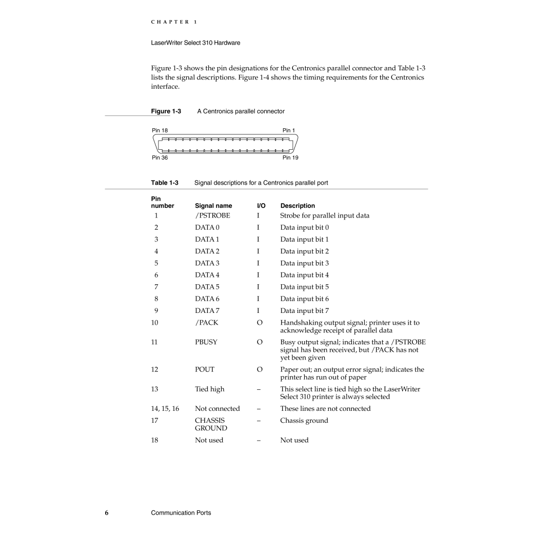
Figure 1-3 shows the pin designations for the Centronics parallel connector and Table 1-3 lists the signal descriptions. Figure 1-4 shows the timing requirements for the Centronics interface.
Figure | A Centronics parallel connector | ||||||
Pin 18 |
|
|
| Pin 1 | |||
|
|
|
|
|
|
| |
|
|
|
|
|
| ||
|
|
|
|
|
| ||
|
|
|
|
|
| ||
Pin 36 |
|
| Pin 19 | ||||
Table | Signal descriptions for a Centronics parallel port | ||||||
|
|
|
|
|
|
| |
Pin |
|
|
|
| |||
number | Signal name | I/O | Description | ||||
1 |
|
|
| /PSTROBE | I | Strobe for parallel input data | |
2 |
|
|
| DATA 0 | I | Data input bit 0 | |
3 |
|
|
| DATA 1 | I | Data input bit 1 | |
4 |
|
|
| DATA 2 | I | Data input bit 2 | |
5 |
|
|
| DATA 3 | I | Data input bit 3 | |
6 |
|
|
| DATA 4 | I | Data input bit 4 | |
7 |
|
|
| DATA 5 | I | Data input bit 5 | |
8 |
|
|
| DATA 6 | I | Data input bit 6 | |
9 |
|
|
| DATA 7 | I | Data input bit 7 | |
10 |
|
|
| /PACK | O | Handshaking output signal; printer uses it to | |
|
|
|
|
|
| acknowledge receipt of parallel data | |
11 |
|
|
| PBUSY | O | Busy output signal; indicates that a /PSTROBE | |
|
|
|
|
|
| signal has been received, but /PACK has not | |
|
|
|
|
|
| yet been given | |
12 |
|
|
| POUT | O | Paper out; an output error signal; indicates the | |
|
|
|
|
|
| printer has run out of paper | |
13 |
|
|
| Tied high | – | This select line is tied high so the LaserWriter | |
|
|
|
|
|
| Select 310 printer is always selected | |
14, 15, 16 | Not connected | – | These lines are not connected | ||||
17 |
|
|
| CHASSIS | – | Chassis ground | |
|
|
|
| GROUND |
|
|
|
18 |
|
|
| Not used | – | Not used | |
6 | Communication Ports |