C H A P T E R 1
LaserWriter Select 310 Hardware
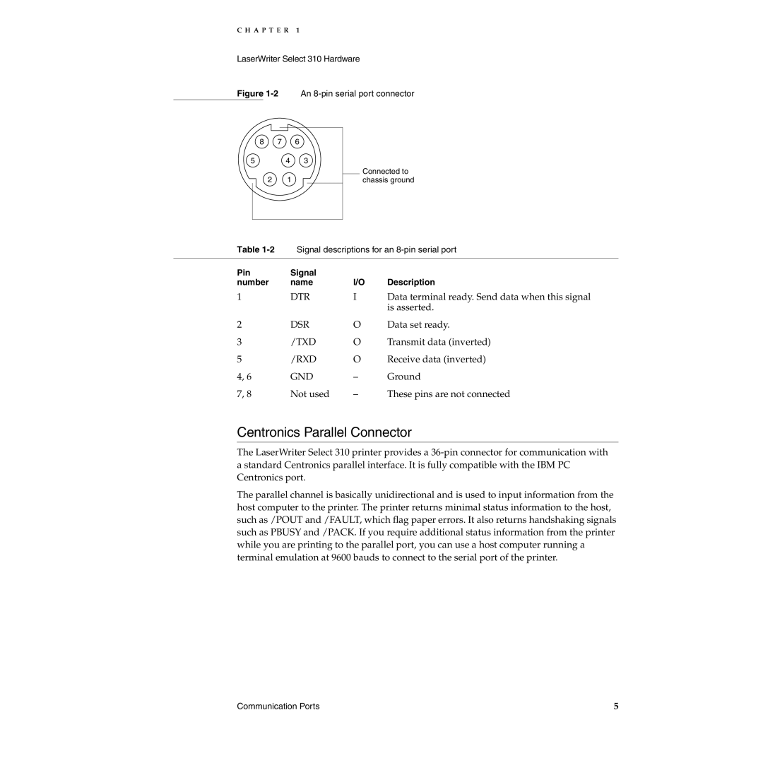
Figure 1-2 An 8-pin serial port connector
8 7 6
5 | 4 | 3 |
2 1
Connected to chassis ground
Table | Signal descriptions for an | ||
|
|
|
|
Pin | Signal |
|
|
number | name | I/O | Description |
1 | DTR | I | Data terminal ready. Send data when this signal |
|
|
| is asserted. |
2 | DSR | O | Data set ready. |
3 | /TXD | O | Transmit data (inverted) |
5 | /RXD | O | Receive data (inverted) |
4, 6 | GND | – | Ground |
7, 8 | Not used | – | These pins are not connected |
Centronics Parallel Connector | 1 |
The LaserWriter Select 310 printer provides a
The parallel channel is basically unidirectional and is used to input information from the host computer to the printer. The printer returns minimal status information to the host, such as /POUT and /FAULT, which flag paper errors. It also returns handshaking signals such as PBUSY and /PACK. If you require additional status information from the printer while you are printing to the parallel port, you can use a host computer running a terminal emulation at 9600 bauds to connect to the serial port of the printer.
Communication Ports | 5 |
