Electrical information - AT-200
Each toaster is equipped with a 4 foot (122 cm), 3 wire grounded power supply cord which terminates with a 3 prong plug
| MODEL NUMBER |
|
| Overall Dimensions with Superfeeder | 18 3/8"H X 15 3/4"W x 26 1/2”D (46.7 cm x 40 cm x 67.4cm) |
|
|
|
| Stock Number/Electrical | |
|
| |
|
| |
|
|
|
| Productivity (Fresh Product) | ( 208V/240V |
| Bun Halves per hour | |
| Bread/toast sliced per hour | ( 208V/240V |
| Croissants per hour | ( 208V/240V |
| English muffins per hour | ( 208V/240V |
Net/Shipping Weight
68 Lbs./75 Lbs. (30.9/34.1 kg)
INSTALLATION - AT SERIES
A.UNPACK UNIT
1.Remove unit from shipping carton, unwrap loose parts and remove any packing tape.
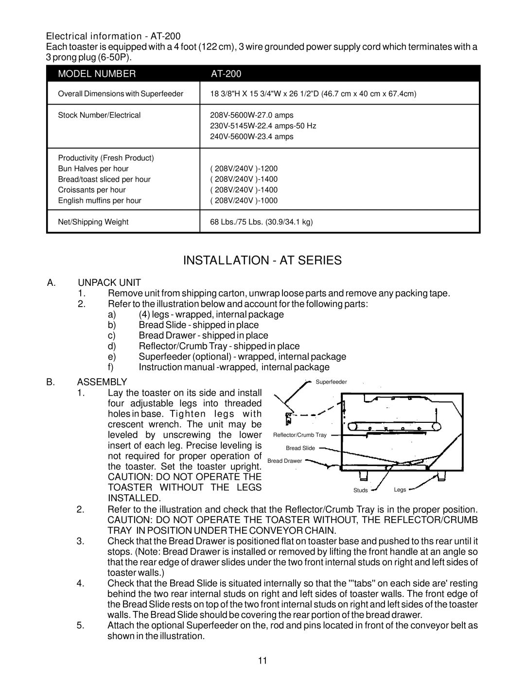
2.Refer to the illustration below and account for the following parts:
a)(4) legs - wrapped, internal package
b)Bread Slide - shipped in place
c)Bread Drawer - shipped in place
d)Reflector/Crumb Tray - shipped in place
e)Superfeeder (optional) - wrapped, internal package
f)Instruction manual
B. | ASSEMBLY | Superfeeder |
| ||
| 1. | Lay the toaster on its side and install |
|
|
|
|
| four adjustable legs into threaded |
|
|
|
|
| holes in base. Tighten legs with |
|
|
|
|
| crescent wrench. The unit may be |
|
|
|
|
| leveled by unscrewing the lower | Reflector/Crumb Tray |
|
|
|
| insert of each leg. Precise leveling is | Bread Slide |
|
|
|
| not required for proper operation of | Bread Drawer |
|
|
|
| the toaster. Set the toaster upright. |
|
|
|
|
| CAUTION: DO NOT OPERATE THE |
|
|
|
|
| TOASTER WITHOUT THE LEGS |
| Studs | Legs |
|
| INSTALLED. |
|
|
|
2.Refer to the illustration and check that the Reflector/Crumb Tray is in the proper position.
CAUTION: DO NOT OPERATE THE TOASTER WITHOUT, THE REFLECTOR/CRUMB TRAY IN POSITION UNDER THE CONVEYOR CHAIN.
3.Check that the Bread Drawer is positioned flat on toaster base and pushed to ths rear until it stops. (Note: Bread Drawer is installed or removed by lifting the front handle at an angle so that the rear edge of drawer slides under the two front internal studs on right and left sides of toaster walls.)
4.Check that the Bread Slide is situated internally so that the '''tabs'' on each side are' resting behind the two rear internal studs on right and left sides of toaster walls. The front edge of the Bread Slide rests on top of the two front internal studs on right and left sides of the toaster walls. The Bread Slide should be covering the rear portion of the bread drawer.
5.Attach the optional Superfeeder on the, rod and pins located in front of the conveyor belt as shown in the illustration.
11