SECTION 4 / SERVICING INSTRUCTIONS
GENERAL LOCATION OF CONTROLS
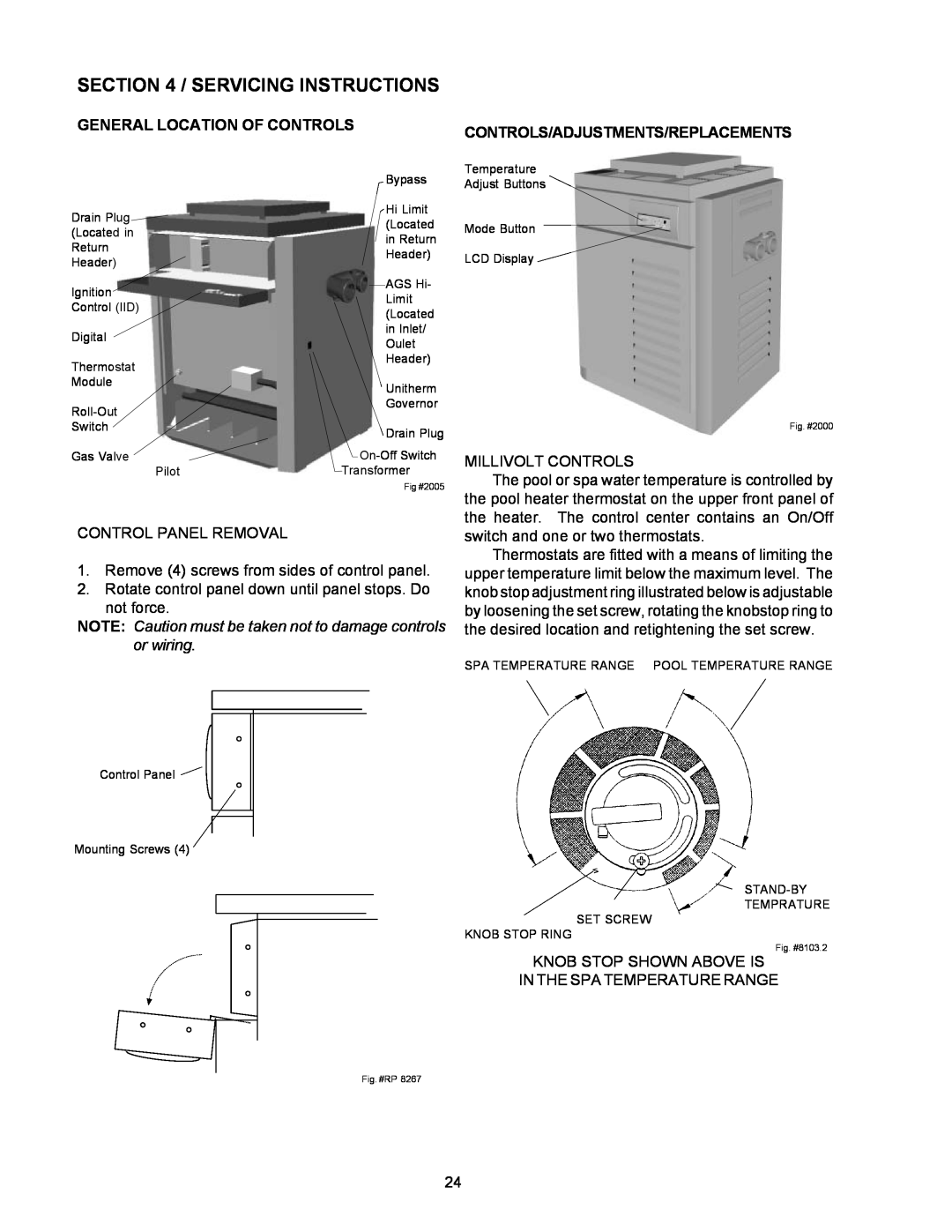
| Bypass | |
Drain Plug | Hi Limit | |
(Located | ||
(Located in | ||
in Return | ||
Return | ||
Header) | ||
Header) | ||
| ||
Ignition | AGS Hi- | |
Limit | ||
Control (IID) | ||
(Located | ||
| ||
Digital | in Inlet/ | |
Oulet | ||
| ||
Thermostat | Header) | |
| ||
Module | Unitherm | |
| ||
Governor | ||
| ||
Switch | Drain Plug | |
| ||
Gas Valve | ||
Pilot | Transformer | |
| Fig #2005 |
CONTROL PANEL REMOVAL
1.Remove (4) screws from sides of control panel.
2.Rotate control panel down until panel stops. Do not force.
NOTE: Caution must be taken not to damage controls or wiring.
Control Panel
Mounting Screws (4)
Fig. #RP 8267
CONTROLS/ADJUSTMENTS/REPLACEMENTS
Temperature
Adjust Buttons
Mode Button
LCD Display
Fig. #2000
MILLIVOLT CONTROLS
The pool or spa water temperature is controlled by the pool heater thermostat on the upper front panel of the heater. The control center contains an On/Off switch and one or two thermostats.
Thermostats are fitted with a means of limiting the upper temperature limit below the maximum level. The knob stop adjustment ring illustrated below is adjustable by loosening the set screw, rotating the knobstop ring to the desired location and retightening the set screw.
SPA TEMPERATURE RANGE POOL TEMPERATURE RANGE
TEMPRATURE
SET SCREW
KNOB STOP RING
Fig. #8103.2
KNOB STOP SHOWN ABOVE IS
IN THE SPA TEMPERATURE RANGE
24