VENT PIPING
WARNING:
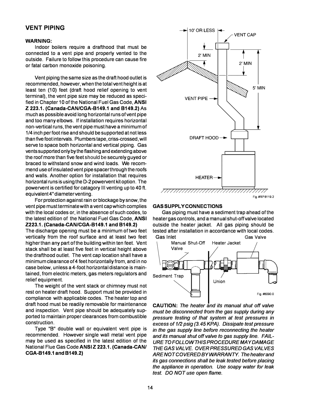
Indoor boilers require a drafthood that must be connected to a vent pipe and properly vented to the outside. Failure to follow this procedure can cause fire or fatal carbon monoxide poisoning.
Vent piping the same size as the draft hood outlet is recommended, however, when the total vent height is at least ten (10) feet (draft hood relief opening to vent terminal), the vent pipe size may be reduced as speci- fied in Chapter 10 of the National Fuel Gas Code, ANSI Z 223.1.
For protection against rain or blockage by snow, the vent pipe must terminate with a vent cap which complies with the local codes or, in the absence of such codes, to the latest edition of the National Fuel Gas Code, ANSI
Z223.1.
The weight of the vent stack or chimney must not rest on heater draft hood. Support must be provided in compliance with applicable codes. The heater top and draft hood must be readily removable for maintenance and inspection. Vent pipe should be adequately sup- ported to maintain proper clearances from combustible construction.
Type "B" double wall or equivalent vent pipe is recommended. However single wall metal vent pipe may be used as specified in the latest edition of the National Flue Gas Code ANSI Z 223.1.
CGA-B149.1 and B149.2)
Fig. #RP 8119.2
GAS SUPPLY CONNECTIONS
Gas piping must have a sediment trap ahead of the heater gas controls, and a manual
Gas InletGas Valve
Manual
Valve
Sediment Trap
Union
Fig. #8090.0
CAUTION: The heater and its manual shut off valve must be disconnected from the gas supply during any pressure testing of that system at test pressures in excess of 1/2 psig (3.45 KPA). Dissipate test pressure in the gas supply line before reconnecting the heater and its manual shut off valve to gas supply line. FAIL-
URE TO FOLLOW THIS PROCEDURE MAY DAMAGE THE GAS VALVE. OVER PRESSURED GAS VALVES ARE NOT COVERED BY WARRANTY. The heater and its gas connections shall be leak tested before placing the appliance in operation. Use soapy water for leak test. DO NOT use open flame.
14