RP2100 REMOTE CONTROL INSTALLATION
CAUTION: Before installing remote controls to the RP2100 Digital Heater, read the following:
The Raypak RP 2100 Digital Heater is remote ready in most cases. The digital liquid crystal (LCD) display shows the actual pool temperature, operating status, and service codes (See examples below). The touch pad on the control panel allows you to select the desired pool or spa temperature. It also indicates when a remote system is controlling the heater by displaying REM in the display. When connecting the RP2100 Digital to a remote system, identify whether it is a two or three wire remote system. Select the appropriate instruction listed below to properly install the remote to the heater.
OFF Mode | Heating in the | Heating in the Remote Mode |
| POOL Mode | SPA Mode |
Remote Wiring Instructions 1.Turn off power to the heater. 2.Turn off gas to the heater.
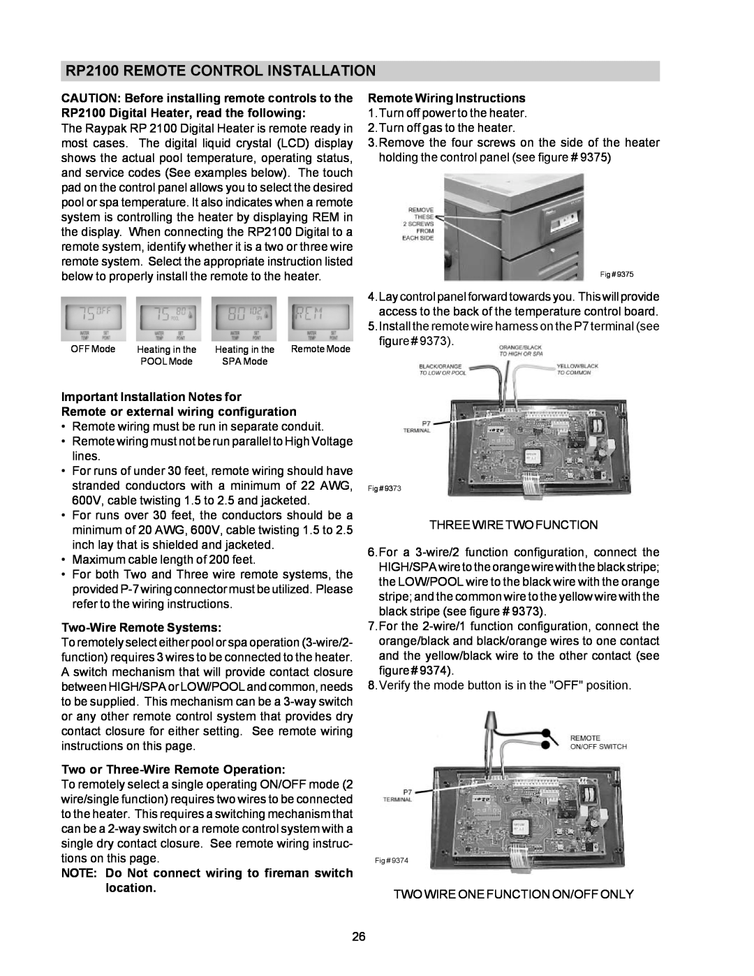
3.Remove the four screws on the side of the heater holding the control panel (see figure # 9375)
Fig # 9375
4.Lay control panel forward towards you. This will provide access to the back of the temperature control board.
5.Install the remote wire harness on the P7 terminal (see figure # 9373).
Important Installation Notes for
Remote or external wiring configuration
•Remote wiring must be run in separate conduit.
•Remote wiring must not be run parallel to High Voltage lines.
•For runs of under 30 feet, remote wiring should have stranded conductors with a minimum of 22 AWG, 600V, cable twisting 1.5 to 2.5 and jacketed.
•For runs over 30 feet, the conductors should be a minimum of 20 AWG, 600V, cable twisting 1.5 to 2.5 inch lay that is shielded and jacketed.
•Maximum cable length of 200 feet.
•For both Two and Three wire remote systems, the provided
Two-Wire Remote Systems:
To remotely select either pool or spa operation
Two or Three-Wire Remote Operation:
To remotely select a single operating ON/OFF mode (2 wire/single function) requires two wires to be connected to the heater. This requires a switching mechanism that can be a
NOTE: Do Not connect wiring to fireman switch location.
Fig # 9373
THREE WIRE TWO FUNCTION
6.For a
7.For the
8.Verify the mode button is in the "OFF" position.
Fig # 9374
TWO WIRE ONE FUNCTION ON/OFF ONLY
26