BURNER DRAWER REMOVAL
1.Shut off main electrical power switch to heater.
2.Shut off gas upstream of heater.
3.Remove front door.
4.Disconnect gas line from gas valve.
5.Remove (2) screws that mount burner tray to unit, and (2) screws that secure gas valve to jacket.
6.Disconnect wires that terminate at gas valve.
7.Slide out burner tray.
8.Reverse above procedure to reinstall.
GAS VALVE REMOVAL
1.Shut off gas supply to the heater. Remove gas piping to gas valve inlet.
2.Disconnect wires, pilot tubing and bleed line, if required.
3.Turn vertical gas pipe from manifold slightly and unscrew gas valve.
4.Reverse above procedure to
MAIN BURNER AND ORIFICE REMOVAL
1.Remove burner drawer. See burner drawer removal procedure.
2.Remove screws and burner hold down bracket.
NOTE: If the heat exchanger is sooted badly, the burner hold down bracket and spacer can become distorted from direct flame impingement and this usually necessitates replacement of these parts.
3.Lift burners from slotted spacers and slide from orifices. Clean with a wire brush.
4.Orifices usually do not need to be replaced. To clean, run either copper wire or wood toothpick through orifice. Do not enlarge hole. To remove orifice, use a socket wrench and remove from manifold. DONOT overtighten when reinstalling.
Burner Hold Down Bracket
Burner
8057.0
PILOT REMOVAL AND CLEANING
1.Disconnect pilot tubing, and wires from gas valve.
2.Remove pilot assembly from burner tray.
3.Remove pilot from bracket.
4.Remove pilot orifice and air opening (Honeywell MV unit only), and clean with wire or small brush.
CAUTION! Do not enlarge hole in pilot orifice.
5. Reverse above procedure to
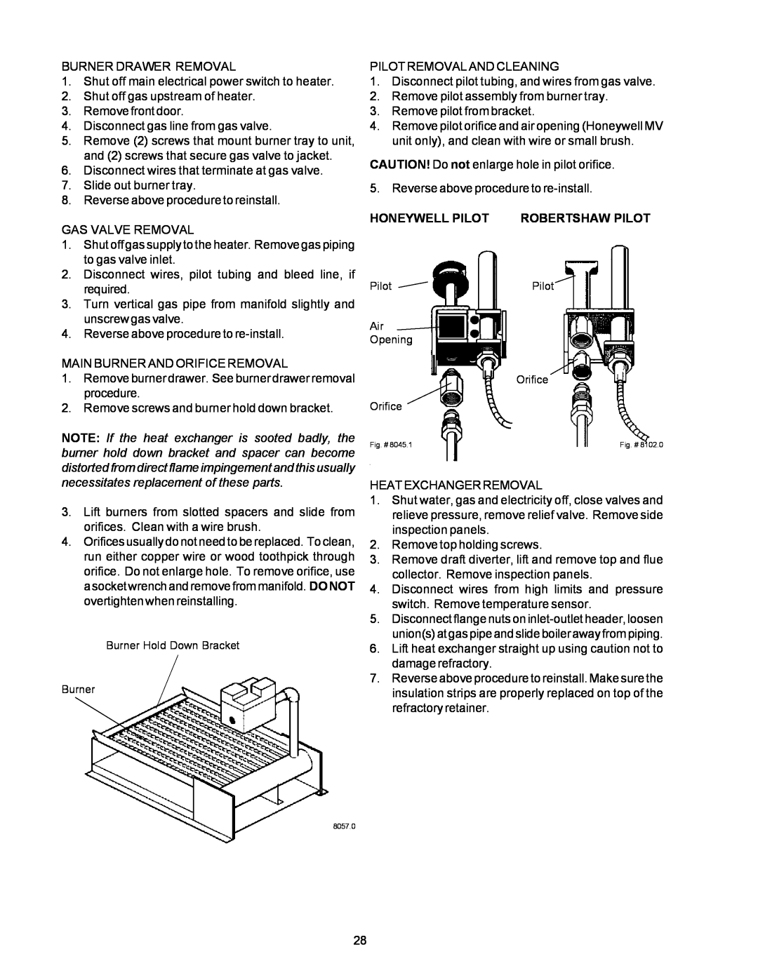
HONEYWELL PILOT ROBERTSHAW PILOT
PilotPilot
Air
Opening
Orifice
Orifice
Fig. # 8045.1 | Fig. # 8102.0 |
HEAT EXCHANGER REMOVAL
1.Shut water, gas and electricity off, close valves and relieve pressure, remove relief valve. Remove side inspection panels.
2.Remove top holding screws.
3.Remove draft diverter, lift and remove top and flue collector. Remove inspection panels.
4.Disconnect wires from high limits and pressure switch. Remove temperature sensor.
5.Disconnect flange nuts on
6.Lift heat exchanger straight up using caution not to damage refractory.
7.Reverse above procedure to reinstall. Make sure the insulation strips are properly replaced on top of the refractory retainer.
28