INDOOR HEATER
The design is also certified for indoor installation when equipped with the approved draft hood.
For Canada, indoor installation is restricted to an enclosure that is not occupied and does not directly communicate with occupied area. Refer to the latest edition of
Locate heater as close as practical to a chimney or gas vent. Heater must always be vented to the outside. See Vent Piping Section for venting details. Minimum allowable space is shown on the nameplate.
WARNING:
Indoor boilers require a drafthood that must be connected to a vent pipe and properly vented to the outside. Failure to follow this procedure can cause fire or fatal carbon monoxide poisioning.
VENT TERMINAL/INDOOR STACK INSTALLATION
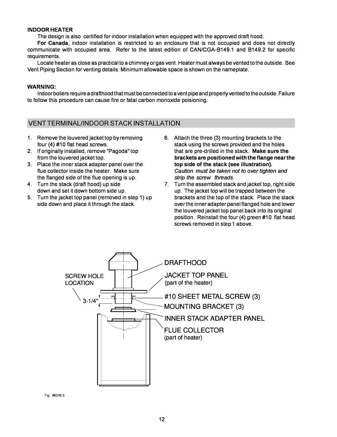
1. | Remove the louvered jacket top by removing | 6. Attach the three (3) mounting brackets to the |
| four (4) #10 flat head screws. | stack using the screws provided and the holes |
2. | If originally installed, remove "Pagoda" top | that are |
| from the louvered jacket top. | brackets are positioned with the flange near the |
3. | Place the inner stack adapter panel over the | top side of the stack (see illustration). |
| flue collector inside the heater. Make sure | Caution must be taken not to over tighten and |
| the flanged side of the flue opening is up. | strip the screw threads. |
4. | Turn the stack (draft hood) up side | 7. Turn the assembled stack and jacket top, right side |
| down and set it down bottom side up. | up. The jacket top will be trapped between the |
5. | Turn the jacket top panel (removed in step 1) up | brackets and the top of the stack. Place the stack |
| side down and place it through the stack. | over the inner adapter panel flanged hole and lower |
|
| the louvered jacket top panel back into its original |
|
| position. Reinstall the four (4) green #10 flat head |
|
| screws removed in step 1 above. |
|
|
|
|
|
|
|
|
| DRAFTHOOD |
SCREW HOLE |
|
|
|
|
|
|
| JACKET TOP PANEL | |
|
|
|
|
|
|
| |||
LOCATION |
|
|
|
|
| (part of the heater) | |||
|
|
|
|
|
|
|
|
| #10 SHEET METAL SCREW (3) |
|
|
|
|
|
|
|
| ||
|
|
|
|
|
|
|
| ||
|
|
|
|
|
|
|
| ||
|
|
|
|
|
|
|
| MOUNTING BRACKET (3) | |
|
|
|
|
|
|
|
|
| |
|
|
|
|
|
| ||||
|
|
|
|
|
|
|
|
| INNER STACK ADAPTER PANEL |
|
|
|
|
|
|
|
|
| FLUE COLLECTOR |
|
|
|
|
|
|
|
|
| (part of heater) |
Fig. #8246.5
12