The Control Unit
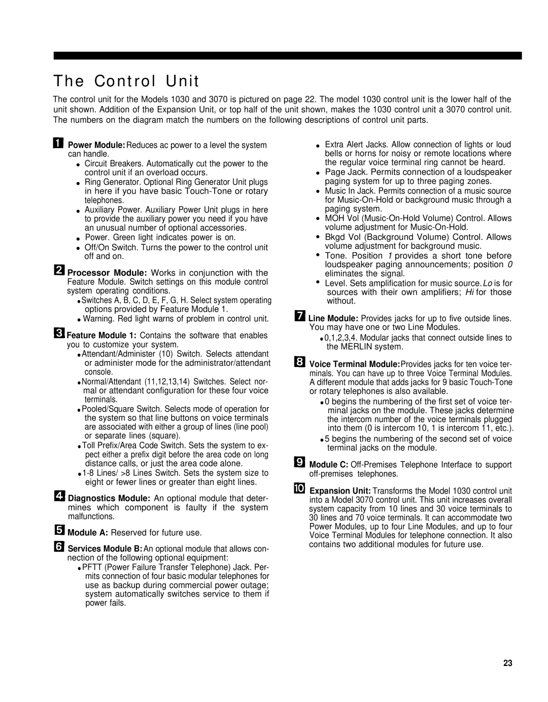
The control unit for the Models 1030 and 3070 is pictured on page 22. The model 1030 control unit is the lower half of the unit shown. Addition of the Expansion Unit, or top half of the unit shown, makes the 1030 control unit a 3070 control unit. The numbers on the diagram match the numbers on the following descriptions of control unit parts.
![]() Power Module: Reduces ac power to a level the system can handle.
Power Module: Reduces ac power to a level the system can handle.
●Circuit Breakers. Automatically cut the power to the control unit if an overload occurs.
●Ring Generator. Optional Ring Generator Unit plugs in here if you have basic
●Auxiliary Power. Auxiliary Power Unit plugs in here to provide the auxiliary power you need if you have an unusual number of optional accessories.
●Power. Green light indicates power is on.
●Off/On Switch. Turns the power to the control unit off and on.
![]() Processor Module: Works in conjunction with the Feature Module. Switch settings on this module control system operating conditions.
Processor Module: Works in conjunction with the Feature Module. Switch settings on this module control system operating conditions.
●Switches A, B, C, D, E, F, G, H. Select system operating options provided by Feature Module 1.
●Warning. Red light warns of problem in control unit.
![]() Feature Module 1: Contains the software that enables you to customize your system.
Feature Module 1: Contains the software that enables you to customize your system.
●Attendant/Administer (10) Switch. Selects attendant or administer mode for the administrator/attendant console.
●Normal/Attendant (11,12,13,14) Switches. Select nor- mal or attendant configuration for these four voice terminals.
●Pooled/Square Switch. Selects mode of operation for the system so that line buttons on voice terminals are associated with either a group of lines (line pool) or separate lines (square).
●Toll Prefix/Area Code Switch. Sets the system to ex- pect either a prefix digit before the area code on long distance calls, or just the area code alone.
●
![]() Diagnostics Module: An optional module that deter- mines which component is faulty if the system malfunctions.
Diagnostics Module: An optional module that deter- mines which component is faulty if the system malfunctions.
![]() Module A: Reserved for future use.
Module A: Reserved for future use.
![]() Services Module B: An optional module that allows con- nection of the following optional equipment:
Services Module B: An optional module that allows con- nection of the following optional equipment:
●PFTT (Power Failure Transfer Telephone) Jack. Per- mits connection of four basic modular telephones for use as backup during commercial power outage; system automatically switches service to them if power fails.
●Extra Alert Jacks. Allow connection of lights or loud bells or horns for noisy or remote locations where the regular voice terminal ring cannot be heard.
●Page Jack. Permits connection of a loudspeaker paging system for up to three paging zones.
●Music In Jack. Permits connection of a music source for
●MOH Vol
●Bkgd Vol (Background Volume) Control. Allows volume adjustment for background music.
●Tone. Position 1 provides a short tone before loudspeaker paging announcements; position 0 eliminates the signal.
●Level. Sets amplification for music source.Lo is for sources with their own amplifiers; Hi for those without.
![]() Line Module: Provides jacks for up to five outside lines. You may have one or two Line Modules.
Line Module: Provides jacks for up to five outside lines. You may have one or two Line Modules.
●0,1,2,3,4. Modular jacks that connect outside lines to the MERLIN system.
![]() Voice Terminal Module:Provides jacks for ten voice ter- minals. You can have up to three Voice Terminal Modules. A different module that adds jacks for 9 basic
Voice Terminal Module:Provides jacks for ten voice ter- minals. You can have up to three Voice Terminal Modules. A different module that adds jacks for 9 basic
●0 begins the numbering of the first set of voice ter- minal jacks on the module. These jacks determine the intercom number of the voice terminals plugged into them (0 is intercom 10, 1 is intercom 11, etc.).
●5 begins the numbering of the second set of voice terminal jacks on the module.
![]() Module C:
Module C:
![]() Expansion Unit: Transforms the Model 1030 control unit into a Model 3070 control unit. This unit increases overall system capacity from 10 lines and 30 voice terminals to 30 lines and 70 voice terminals. It can accommodate two Power Modules, up to four Line Modules, and up to four Voice Terminal Modules for telephone connection. It also contains two additional modules for future use.
Expansion Unit: Transforms the Model 1030 control unit into a Model 3070 control unit. This unit increases overall system capacity from 10 lines and 30 voice terminals to 30 lines and 70 voice terminals. It can accommodate two Power Modules, up to four Line Modules, and up to four Voice Terminal Modules for telephone connection. It also contains two additional modules for future use.
23