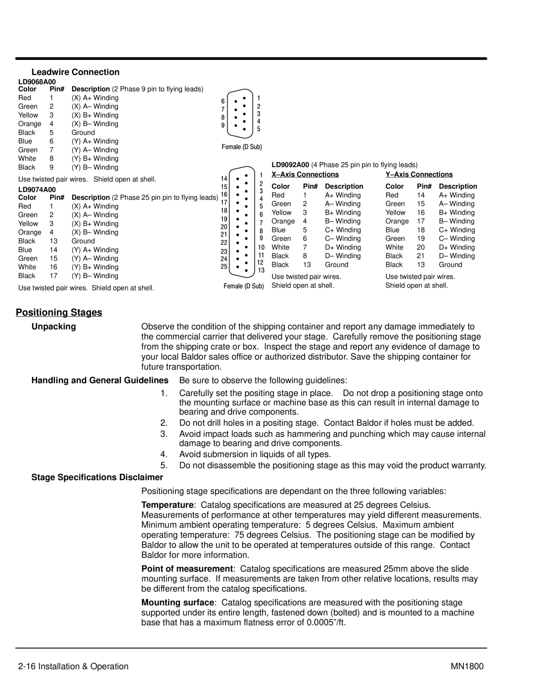
Baldor iMN1800 manual Positioning Stages, Unpacking, Stage Specifications Disclaimer

Models: iMN1800

1 48
Download 48 pages 59.56 Kb
Page 23
Image 23

Leadwire Connection

LD9068A00


Color

Pin#

Description (2 Phase 9 pin to flying leads)


Red

1

(X) A+ Winding

6


1


Green

2

(X) A– Winding


2


7


Yellow

3

(X) B+ Winding


3


8


Orange

4

(X) B– Winding


4


9


5


Black

5

Ground


Blue

6

(Y) A+ Winding

Female (D Sub)


Green

7

(Y) A– Winding


White

8

(Y) B+ Winding


LD9092A00 (4 Phase 25 pin pin to flying leads)


Black

9

(Y) B– Winding


X–Axis Connections

Y–Axis Connections

Use twisted pair wires. Shield open at shell.

14


1


2

Color

Pin#

Description

Color

Pin#

Description

LD9074A00


15


16


3

Red

1

A+ Winding

Red

14

A+ Winding

Color

Pin#

Description (2 Phase 25 pin pin to flying leads)


4

Red

1

(X) A+ Winding

17


5

Green

2

A– Winding

Green

15

A– Winding

18


Yellow

3

B+ Winding

Yellow

16

B+ Winding

Green

2

(X) A– Winding


6

19


Orange

4

B– Winding

Orange

17

B– Winding

Yellow

3

(X) B+ Winding


7

20


Blue

5

C+ Winding

Blue

18

C+ Winding

Orange

4

(X) B– Winding


8

21


Green

6

C– Winding

Green

19

C– Winding

Black

13

Ground


9

22


10

White

7

D+ Winding

White

20

D+ Winding

Blue

14

(Y) A+ Winding

23


11

Black

8

D– Winding

Black

21

D– Winding

Green

15

(Y) A– Winding


24


12

Black

13

Ground

Black

13

Ground

White

16

(Y) B+ Winding

25


13


Black

17

(Y) B– Winding


Use twisted pair wires.

Use twisted pair wires.


Use twisted pair wires. Shield open at shell.

Female (D Sub) Shield open at shell.

Shield open at shell.

Positioning Stages

Unpacking

Observe the condition of the shipping container and report any damage immediately to


the commercial carrier that delivered your stage. Carefully remove the positioning stage


from the shipping crate or box. Inspect the stage and report any evidence of damage to


your local Baldor sales office or authorized distributor. Save the shipping container for


future transportation.

Handling and General Guidelines Be sure to observe the following guidelines:

1.Carefully set the positing stage in place. Do not drop a positioning stage onto the mounting surface or machine base as this can result in internal damage to bearing and drive components.

2.Do not drill holes in a positing stage. Contact Baldor if holes must be added.

3.Avoid impact loads such as hammering and punching which may cause internal damage to bearing and drive components.

4.Avoid submersion in liquids of all types.

5.Do not disassemble the positioning stage as this may void the product warranty.

Stage Specifications Disclaimer

Positioning stage specifications are dependant on the three following variables:

Temperature: Catalog specifications are measured at 25 degrees Celsius. Measurements of performance at other temperatures may yield different measurements. Minimum ambient operating temperature: 5 degrees Celsius. Maximum ambient operating temperature: 75 degrees Celsius. The positioning stage can be modified by Baldor to allow the unit to be operated at temperatures outside of this range. Contact Baldor for more information.

Point of measurement: Catalog specifications are measured 25mm above the slide mounting surface. If measurements are taken from other relative locations, results may be different from the catalog specifications.

Mounting surface: Catalog specifications are measured with the positioning stage supported under its entire length, fastened down (bolted) and is mounted to a machine base that has a maximum flatness error of 0.0005”/ft.

2-16 Installation & Operation

MN1800

Page 23
Image 23
Baldor iMN1800 manual Positioning Stages, Unpacking, Stage Specifications Disclaimer

iMN1800 specifications

The Baldor iMN1800 is a comprehensive industrial motor drive, engineered for a wide range of applications in various sectors such as manufacturing, robotics, and automation. This drive exemplifies Baldor's commitment to innovation, performance, and efficiency, offering users advanced features that cater to modern industrial demands.

At the heart of the iMN1800 is its state-of-the-art motor control technology, designed to provide precise control over motor speed and torque. This is achieved through a sophisticated algorithm that adjusts the motor's performance in real-time, ensuring reliability and efficiency. The iMN1800 is compatible with various forms of electric motors, including AC induction and permanent magnet synchronous motors, making it versatile for numerous applications.

One of the standout features of the Baldor iMN1800 is its energy efficiency. It complies with various energy standards, which not only helps reduce operational costs but also minimizes the environmental impact associated with industrial operations. With an impressive efficiency rating, the iMN1800 contributes to lower energy consumption, making it an economically viable solution for businesses aiming to enhance sustainability.

In terms of connectivity, the iMN1800 incorporates advanced communication protocols such as Ethernet/IP and Modbus, allowing for seamless integration into existing industrial networks. This feature facilitates real-time monitoring and control, empowering operators to make informed decisions based on live data. The user-friendly interface enables quick access to essential parameters for both configuration and diagnostics, ensuring ease of use for technicians and engineers alike.

Moreover, the iMN1800 is built with robust construction materials, ensuring durability in demanding environments. Its rugged design allows it to withstand harsh conditions, including high temperatures and vibrations, common in industrial settings. This reliability contributes to reduced downtime and maintenance costs, promoting a more productive work environment.

The Baldor iMN1800 also features advanced safety mechanisms, including overload protection and short-circuit protection, guaranteeing the safety of both personnel and equipment. These attributes align with modern safety standards, making it a trusted choice for industries that prioritize workplace safety.

In summary, the Baldor iMN1800 is a top-tier industrial motor drive that combines advanced motor control technology, energy efficiency, robust construction, and enhanced safety features. Its flexibility and connectivity make it a valuable asset for diverse industrial applications, ultimately driving operational efficiency and effectiveness.