Installation Mode
800 Peripheral
Output module selection.
When a RCVDS05 is connected to the projector, the type of output module of this RCVDS05 has to be defined in the 800 peripheral menu.
The type of output module can be :
-standard output module or
-5 cable output module. To define the output module :
1 Push the cursor key or to highlight '800 Peripheral'.
2 Press ENTER to select.
3 Push the cursor key or to highlight 'Output module'.
4 Press ENTER to toggle between 'Standard' or
Infrared Communication.
When a peripheral is connected to the 'Comm Port', the communica- tion can be in PPM or RC5.
The type of communication can be set to :
-PPM
-RC5
To define the communication :
1Push the cursor key or to highlight 'Infrared'.
2 Press ENTER to select.
3.Press ENTER to toggle between [PPM] or [RC5].Configuration
Convergence
To start the convergence adjustment :
1Push the cursor key or to highlight 'convergence'.
2 Press ENTER to select.
Every LCD panel has 6 motorized adjustments. These motorized adjustments can be adjusted with your RCU in your hand, while you are standing next to the screen. By changing the position of these servo motors, you change the relative position of the panels and converge the image.
Always start with the adjustment of the green panel. When the green image is correctly focused, it will later on be used as the reference image to converge the red and blue image.
The following alignments have to be done :
You have to adjust the green panel until the indicated lines on the screen are focused (sharp lines). Continue with the blue panel and adjust until the blue lines coincide with the green lines. Than continue with the red panel until the red lines coincide with the green lines.
If there is a total misalignment of the convergence or when the panels are replaced, start with green to midposition and continue then with the normal alignment of Green, Blue on green and Red on green.
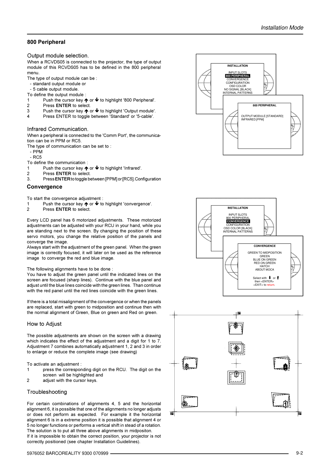
How to Adjust
The possible adjustments are shown on the screen with a drawing which indicates the effect of the adjustment and a digit for 1 to 7. Adjustment 7 combines automatically adjustment 1, 2 and 3 in order to enlarge or reduce the complete image (see drawing)
To activate an adjustment :
1press the corresponding digit on the RCU. The digit on the screen will be highlighted and
2adjust with the cursor keys.
Troubleshooting
For certain combinations of alignments 4, 5 and the horizontal alignment 6, it is possible that one of the alignments no longer adjusts or does not perform as expected. For example it the horizontal alignment 6 is in a extreme position it is possible that alignment 4 or 5 no longer functions or performs a vertical shift in stead of a rotation. The solution is to put all three above alignments in midpositon.
If it is impossible to obtain the correct position, your projector is not correctly positioned (see chapter Installation Guidelines).
5976052 BARCOREALITY 9300 070999
INSTALLATION
INPUT SLOTS
800 PERIPHERAL
CONVERGENCE
CONFIGURATION
OSD COLOR
NO SIGNAL [BLACK]
INTERNAL PATTERNS
Select with | or |
then <ENTER> | |
<EXIT> to | 800 PERIPHERAL |
OUTPUT MODULE [STANDARD]
INFRARED [PPM]
INSTALLATION |
| |
INPUT SLOTS |
| |
800 PERIPHERAL |
| |
CONVERGENCE |
| |
CONFIGURATION |
| |
OSD COLOR [BLACK] |
| |
INTERNAL PATTERNS |
| |
Select with | or |
|
then <ENTER> |
| |
<EXIT> | CONVERGENCE | |
| GREEN TO MIDPOSITION | |
| GREEN |
|
| BLUE ON GREEN | |
| RED ON GREEN | |
| HATCH |
|
| ABOUT MOCA | |
| Select with | or |
| then <ENTER> | |
| <EXIT> to return. | |