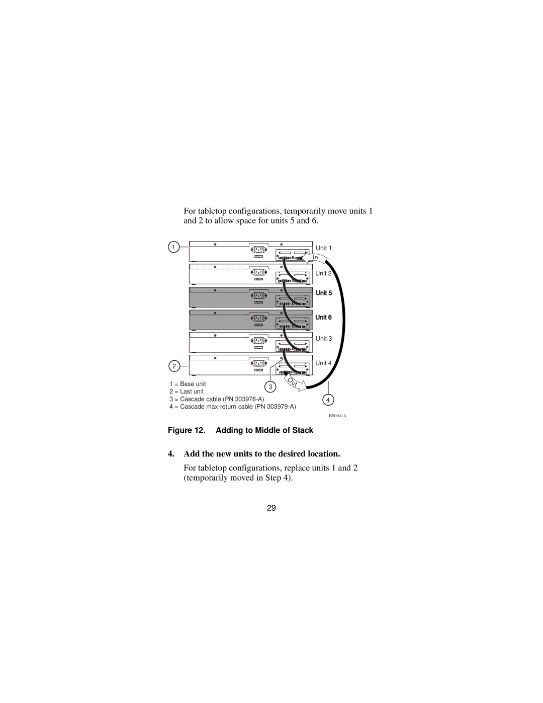
For tabletop configurations, temporarily move units 1 and 2 to allow space for units 5 and 6.
1
2
|
|
| O |
1 | = Base unit |
| u |
3 | t | ||
2 | = Last unit |
| |
|
| ||
3 | = Cascade cable (PN |
|
|
4 | = Cascade | ||
Unit 1
In
Unit 2
Unit 3
Unit 4
4
BS0041A
Figure 12. Adding to Middle of Stack
4.Add the new units to the desired location.
For tabletop configurations, replace units 1 and 2 (temporarily moved in Step 4).
29