Cas Pwr Up
Status Dwn
Cas Pwr Up
Status Dwn
RPSU Base | RPSU Base | |
1 |
| 2 |
11 | 12 |
|
| BayStack | |
23 | 24 |
|
| Cas |
|
1 = Base unit only
2 = All other units in stack
BS0040A
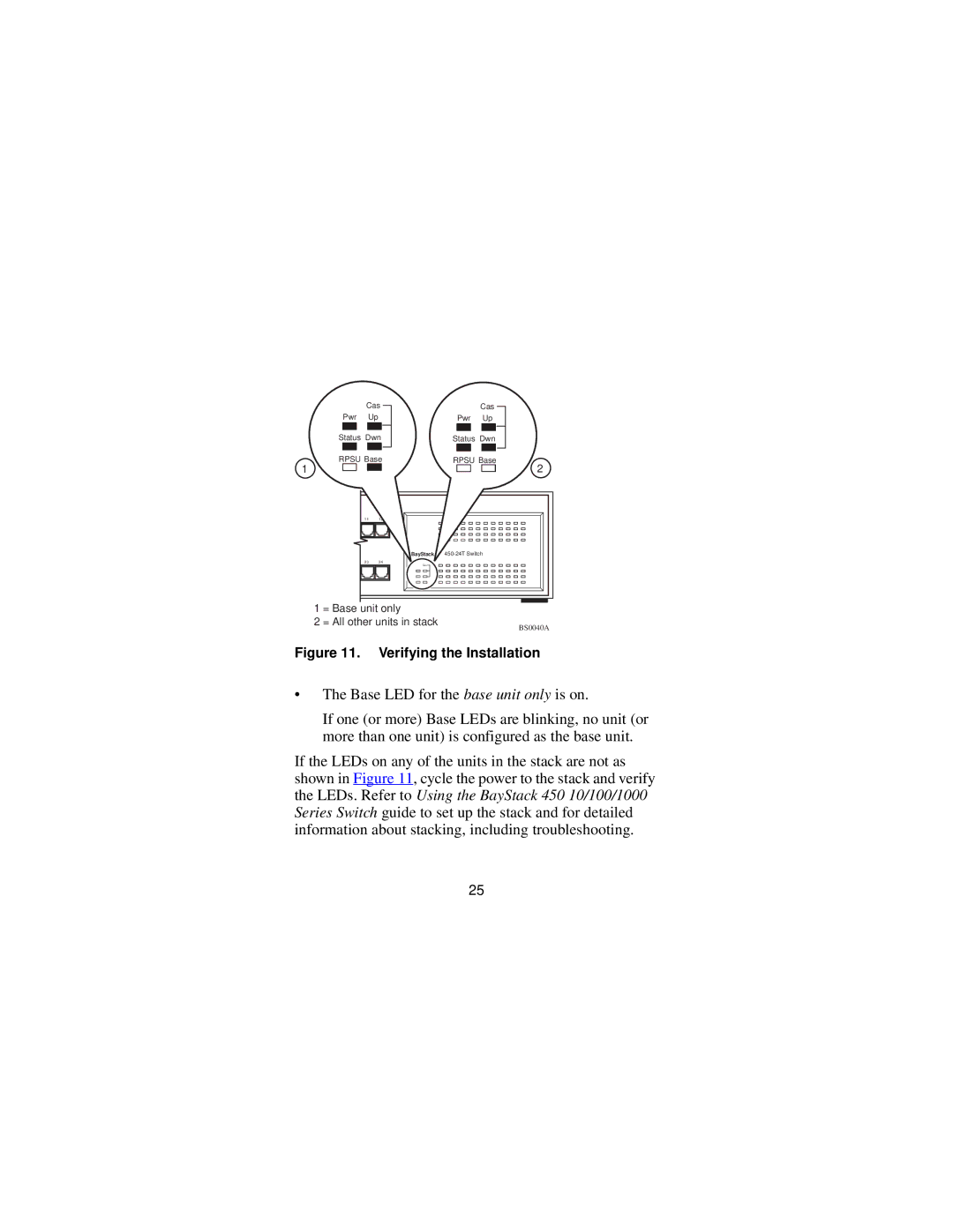
Figure 11. Verifying the Installation
•The Base LED for the base unit only is on.
If one (or more) Base LEDs are blinking, no unit (or more than one unit) is configured as the base unit.
If the LEDs on any of the units in the stack are not as shown in Figure 11, cycle the power to the stack and verify the LEDs. Refer to Using the BayStack 450 10/100/1000 Series Switch guide to set up the stack and for detailed information about stacking, including troubleshooting.
25