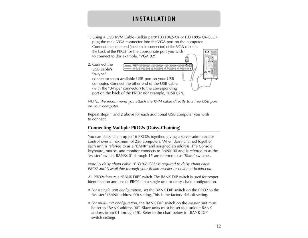
1. Using a USB KVM Cable (Belkin part# F3X1962-XX or F3X1895-XX-GLD), plug the male VGA connector into the VGA port on the computer. Connect the other end (the female connector) of the VGA cable to
the back of the PRO2 for the appropriate port you wish to connect to (for example, "VGA 02").
2. Connect the
VGA | VGA08 | USB08 | VGA07 | 06 VGA 06 | USB 06 | VGA05 | VGA04 | USB 04 | VGA03 | VGA 02 | USB 02 | VGA01 |
USB cable's | 08 | USB 07 | 07 | 06 | USB 05 | 05 | 04 | USB 03 | 03 | 02 | USB 01 | 01 |
"A-type"
 connector to an available USB port on your USB computer. Connect the other end of the USB cable (with the "B-type" connector) to the corresponding port on the back of the PRO2 (for example, "USB 02").
NOTE: We recommend you attach the KVM cable directly to a free USB port on your computer.
Repeat steps 1 and 2 above for each additional USB computer you wish to connect.
Connecting Multiple PRO2s (Daisy-Chaining)
You can daisy-chain up to 16 PRO2s together, giving a server administrator control over a maximum of 256 computers. When daisy-chained together, each unit is referred to as a "BANK" and assigned an address. The Console keyboard, mouse, and monitor connects to BANK 00 and is referred to as the "Master" switch. BANKs 01 through 15 are referred to as "Slave" switches.
Note: A daisy-chain cable (F1D108-CBL) is required to daisy-chain each PRO2 and is available through your Belkin reseller or online at belkin.com.
All PRO2s feature a “BANK DIP” switch. The BANK DIP switch is used for proper identification and use of PRO2s in a single-unit or daisy-chain configuration.
•For a single-unit configuration, set the BANK DIP switch on the PRO2 to the “Master” (BANK address 00) setting. This is the factory default setting.
•For multi-unit configuration, the BANK DIP switch on the Master unit must be set to “BANK address 00”. Slave units must be set to a unique BANK address (from 01 through 15). Refer to the chart below for BANK DIP switch settings.