Parts/kits listed are now obsolete and are no longer serviceable through Bendix.
Display Bracket Replacement - CB Style Mount (Dashboard)
1.Unscrew and disconnect the
2.Unscrew the threaded knobs from the display and brackets. Set the display, knobs, and washers aside. Exercise care to prevent dropping the washers into the venting on the dash.
3.Remove the four #10 Plastite® pan head screws from the brackets and dashboard. Set the four screws aside.
4.Secure the replacement brackets with the four screws from Step 3.
5.Torque the screws to approximately 20
6.Slide one of the washers onto one of the threaded knobs.
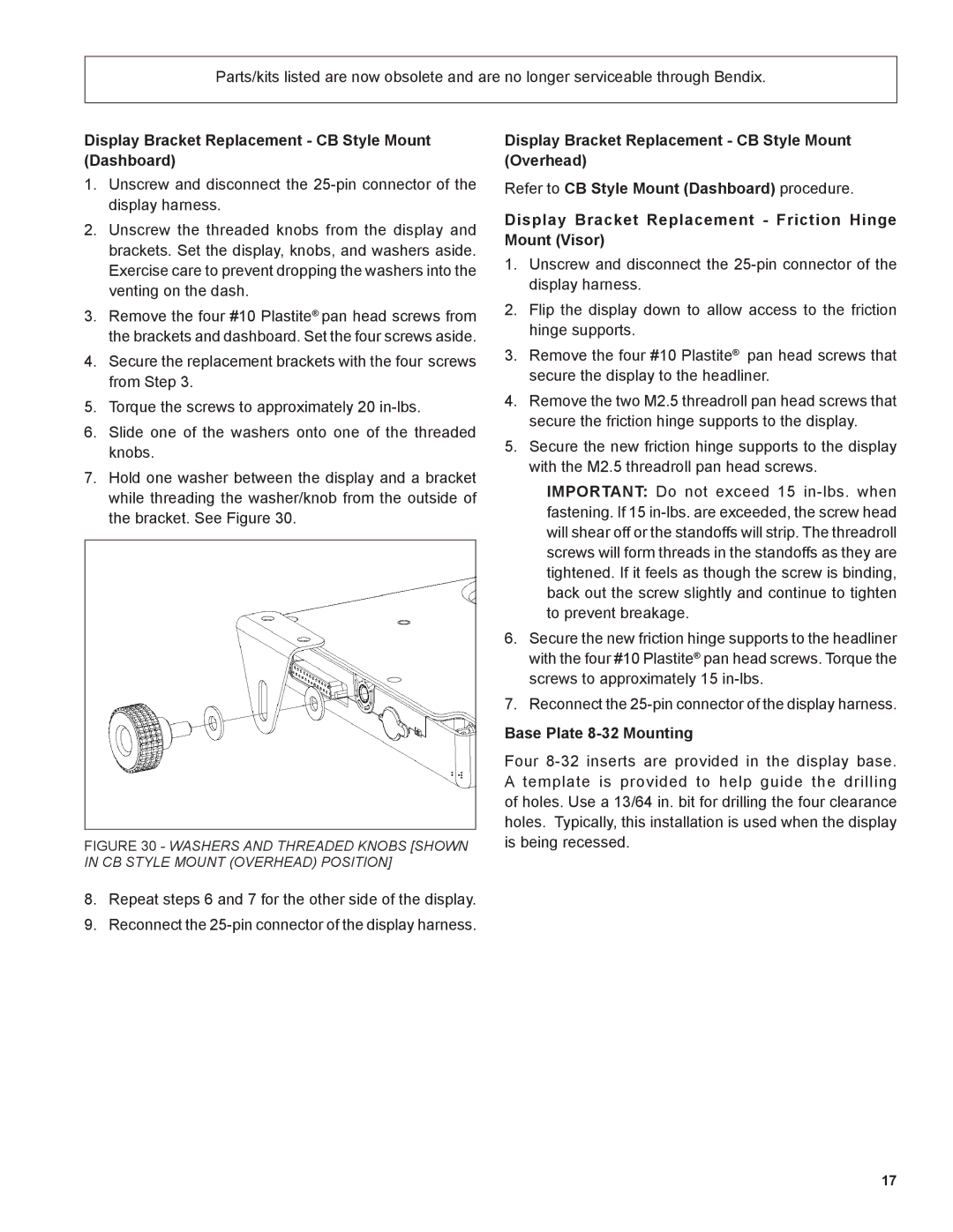
7.Hold one washer between the display and a bracket while threading the washer/knob from the outside of the bracket. See Figure 30.
FIGURE 30 - WASHERS AND THREADED KNOBS [SHOWN IN CB STYLE MOUNT (OVERHEAD) POSITION]
8.Repeat steps 6 and 7 for the other side of the display.
9.Reconnect the
Display Bracket Replacement - CB Style Mount (Overhead)
Refer to CB Style Mount (Dashboard) procedure.
Display Bracket Replacement - Friction Hinge Mount (Visor)
1.Unscrew and disconnect the
2.Flip the display down to allow access to the friction hinge supports.
3.Remove the four #10 Plastite® pan head screws that secure the display to the headliner.
4.Remove the two M2.5 threadroll pan head screws that secure the friction hinge supports to the display.
5.Secure the new friction hinge supports to the display with the M2.5 threadroll pan head screws.
IMPORTANT: Do not exceed 15
6.Secure the new friction hinge supports to the headliner with the four #10 Plastite® pan head screws. Torque the screws to approximately 15
7.Reconnect the
Base Plate 8-32 Mounting
Four
17