Parts/kits listed are now obsolete and are no longer serviceable through Bendix.
VERTICAL AIMING AND ADJUSTING
The virtual image should be aligned vertically so that the horizon appears in the lower
The vertical aiming adjusters can accommodate approximately ±4 degrees of movement. If the IR camera needs more than 4 degrees of vertical movement the IR camera bracket will need to be adjusted. Before changing the vertical aiming adjuster, make sure the 5/16 bolts of the IR camera bracket are tightened to
1.Using Figures 39 - 42 and a T15 Torx wrench, adjust the angle of the IR camera as needed.
NOTE: Two turns of the vertical adjuster is equal to one degree of IR camera movement.
NOTE: It is recommended that the IR camera adjusters be aimed to view approximately 200 ft (61m) in front of the vehicle. Any thermal objects closer than 200 feet will already be illuminated by the low beam headlamps.
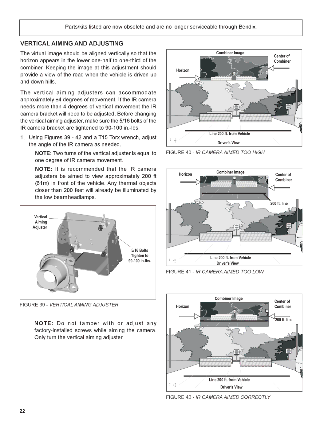
Vertical
Aiming
Adjuster
5/16 Bolts Tighten to
FIGURE 39 - VERTICAL AIMING ADJUSTER
NOTE: Do not tamper with or adjust any
Combiner Image | Center of |
| |
| Combiner |
Horizon |
|
Line 200 ft. from Vehicle |
|
Driver’s View |
|
FIGURE 40 - IR CAMERA AIMED TOO HIGH
Horizon | Combiner Image | Center of |
| ||
|
| Combiner |
|
| 200 ft. line |
| Line 200 ft. from Vehicle |
|
| Driver’s View |
|
FIGURE 41 - IR CAMERA AIMED TOO LOW
| Combiner Image | Center of |
|
| |
Horizon |
| Combiner |
|
| 200 ft. line |
| Line 200 ft. from Vehicle |
|
| Driver’s View |
|
FIGURE 42 - IR CAMERA AIMED CORRECTLY
22