Parts/kits listed are now obsolete and are no longer serviceable through Bendix.
wrench to approximately 15 to 20
16.Route the IR camera harness to the “A” pillar of the cab.
17.Connect the
Heat Shrinkable Shroud |
Externally |
Threaded Nut |
. |
in |
3 |
(Approximately) |
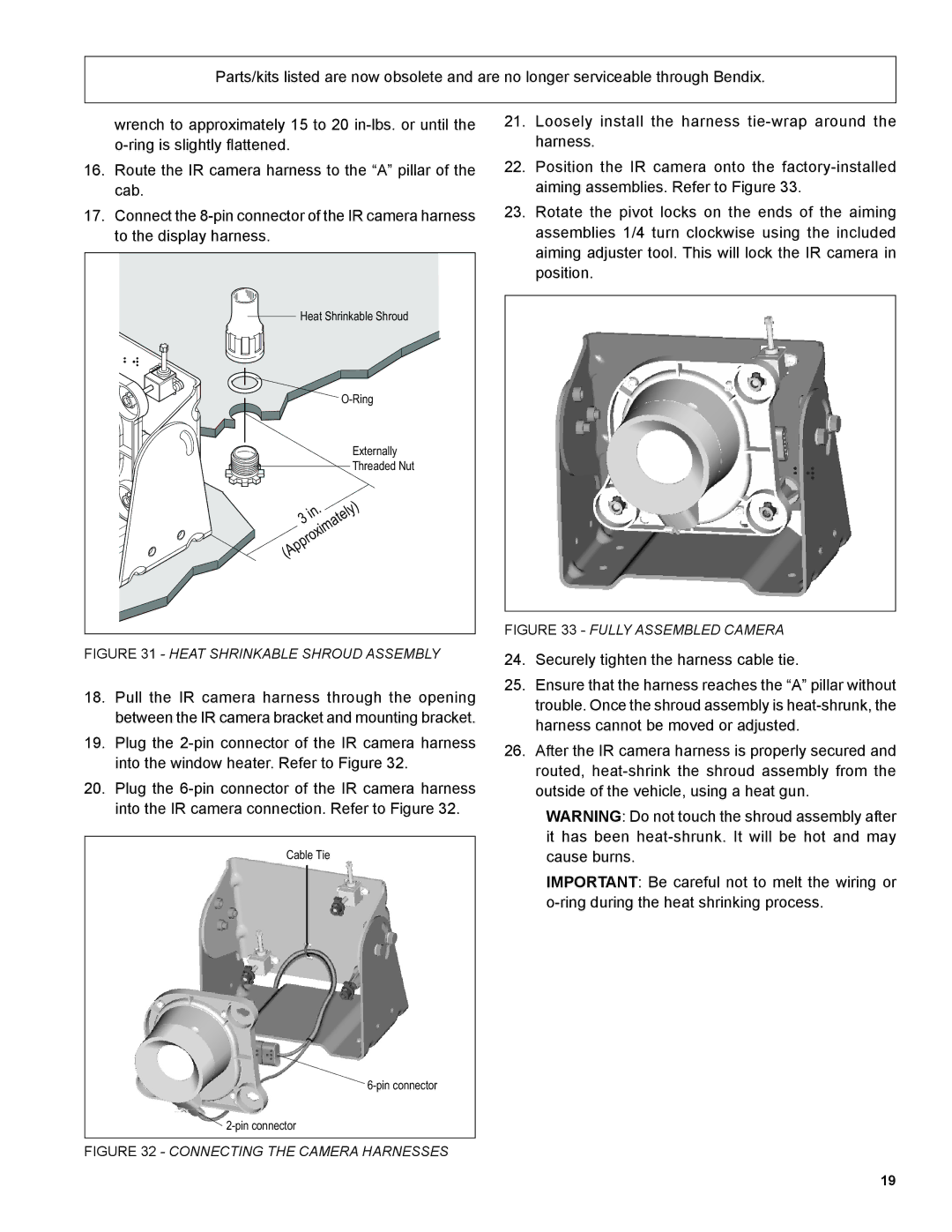
FIGURE 31 - HEAT SHRINKABLE SHROUD ASSEMBLY
18.Pull the IR camera harness through the opening between the IR camera bracket and mounting bracket.
19.Plug the
20.Plug the
Cable Tie
21.Loosely install the harness
22.Position the IR camera onto the
23.Rotate the pivot locks on the ends of the aiming assemblies 1/4 turn clockwise using the included aiming adjuster tool. This will lock the IR camera in position.
FIGURE 33 - FULLY ASSEMBLED CAMERA
24.Securely tighten the harness cable tie.
25.Ensure that the harness reaches the “A” pillar without trouble. Once the shroud assembly is
26.After the IR camera harness is properly secured and routed,
WARNING: Do not touch the shroud assembly after it has been
IMPORTANT: Be careful not to melt the wiring or
![]()
FIGURE 32 - CONNECTING THE CAMERA HARNESSES
19
