3. Operation
3.1 Overview
You can operate the BRTS-100 ISDN Test Set in a variety of modes. Select them by turning the selector dial on the left of the unit (see Figure 3-1). The indicator lights (LEDs) on top of the unit indicate test results. The various test modes and indicator lights are explained in more detail below.
3.2 Connecting the Unit
In the shipping box, you’ll find:
•The BRTS-100 ISDN Test Set.
•(1) 9-volt battery.
•An RJ-45-to-RJ-45 cable.
•(4) RJ-45-to-alligator-clips cable.
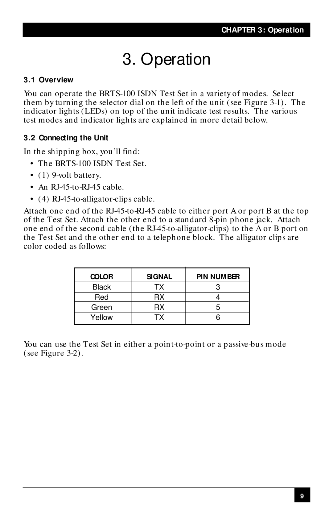
Attach one end of the RJ-45-to-RJ-45 cable to either port A or port B at the top of the Test Set. Attach the other end to a standard 8-pin phone jack. Attach one end of the second cable (the RJ-45-to-alligator-clips) to the A or B port on the Test Set and the other end to a telephone block. The alligator clips are color coded as follows:
COLOR | SIGNAL | PIN NUMBER |
Black | TX | 3 |
| | |
Red | RX | 4 |
Green | RX | 5 |
Yellow | TX | 6 |
| | |
You can use the Test Set in either a point-to-point or a passive-bus mode (see Figure 3-2).