6 x 4 ELECTRONIC SCSI SWITCH
To access jumper options:
Remove the six screws on the bottom of the unit. Then lift off the cover.
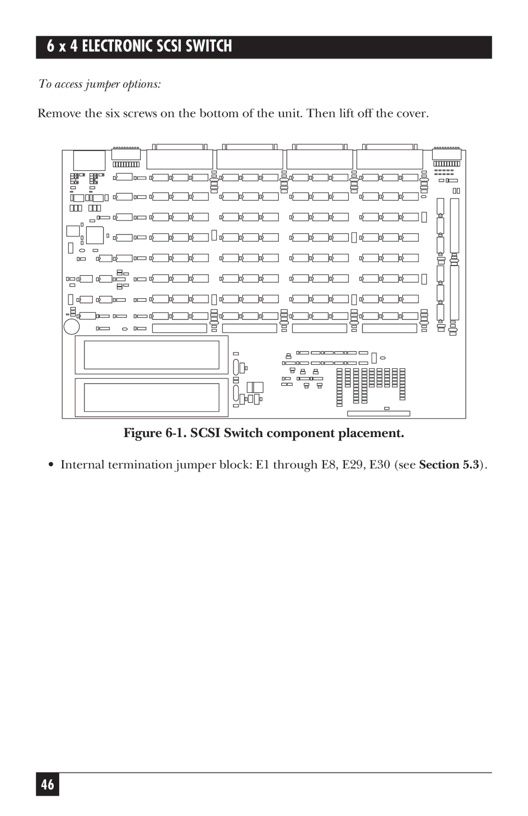
Figure 6-1. SCSI Switch component placement.
• Internal termination jumper block: E1 through E8, E29, E30 (see Section 5.3).
46