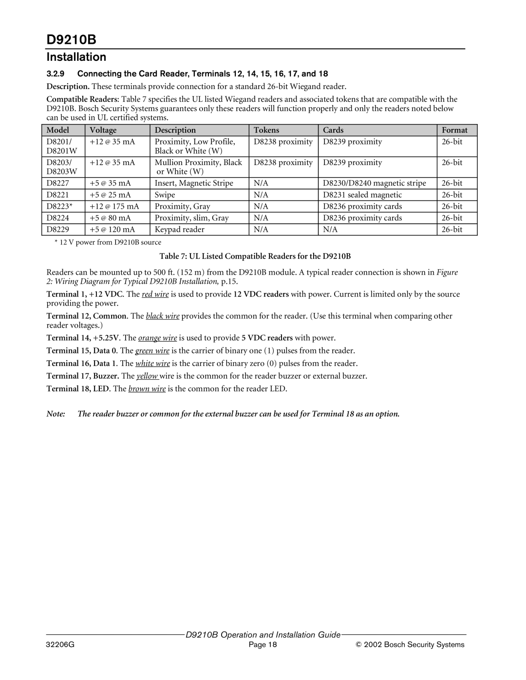
D9210B specifications
The Bosch Appliances D9210B is a remarkable addition to any modern kitchen, reflecting the brand's long-standing commitment to quality, innovation, and performance. This appliance, often revered for its versatility and user-friendly design, embodies the essence of Bosch's engineering excellence.One of the standout features of the D9210B is its sleek and sophisticated design. With a streamlined appearance, it can seamlessly integrate into various kitchen styles, from contemporary to traditional. The stainless steel finish not only adds a touch of elegance but also ensures durability and ease of maintenance.
The D9210B is equipped with advanced cooking technologies that cater to both novice cooks and seasoned chefs. It boasts a powerful convection heating system, ensuring even heat distribution for perfectly cooked meals. This technology enables faster cooking times and promotes energy efficiency, making it an environmentally friendly choice. Users can enjoy the advantages of precision cooking, allowing for a wider range of culinary techniques and styles.
Another essential feature of the Bosch D9210B is its intuitive control system. The easy-to-use digital display allows users to select and adjust settings with precision. The sensor technology automatically adjusts cooking times and temperatures, ensuring optimal results with minimal effort.
Safety is also a top priority with the D9210B. It is designed with several safety mechanisms, including automatic shut-off and a safety lock to prevent unintended use, making it a reliable appliance for families.
In addition to its functional attributes, the Bosch D9210B places great emphasis on energy efficiency. The appliance is designed to minimize energy consumption without sacrificing performance, contributing to lower utility bills and a reduced carbon footprint.
Maintenance is made easy with the D9210B. The appliance features removable components that are dishwasher safe, allowing for a straightforward cleaning process. Furthermore, Bosch's reputation for reliability ensures that users can count on this appliance for years of trouble-free operation.
Overall, the Bosch Appliances D9210B exemplifies a perfect balance of style, efficiency, and advanced cooking technology, making it an excellent investment for any kitchen. It is a symbol of the brand's dedication to enhancing culinary experiences while maintaining the highest standards of quality and innovation.

