Applications manual | 35 |
|
|
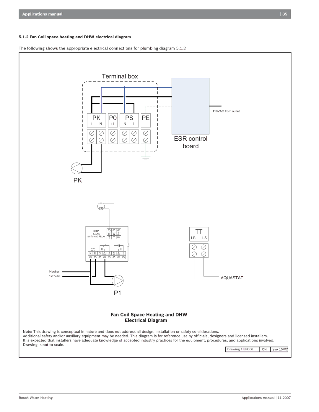
5.1.2 Fan Coil space heating and DHW electrical diagram
The following shows the appropriate electrical connections for plumbing diagram 5.1.2
| Terminal box |
| |||
PK | P0 | PS | PE | ||
L | N | LL | N | L |
|
ESR control
board
110VAC from outlet
PK
T
Stat
| SR501 |
| R | W VAC24 |
| |||
| 1 ZONE |
|
| |||||
SWITCHING RELAY | T | T | COM |
| ||||
120 VAC |
|
|
|
|
|
| ||
INPUT |
| 4 | 4 | 6 | 6 |
| ||
N | H | 3 | 5 | |||||
N/O | N/C | N/C | N/O | |||||
Neutral
120Vac
TT
LR LS
AQUASTAT
P1
Fan Coil Space Heating and DHW
Electrical Diagram
Note: This drawing is conceptual in nature and does not address all design, installation or safety considerations.
Additional safety and/or auxiliary equipment may be needed. This diagram is for reference use by officials, designers and licensed installers.
It is expected that installers have adequate knowledge of accepted industry practices for the equipment, procedures, and applications involved. Drawing is not to scale.
Drawing # EFCOL | CN | revA 10/07 |
Bosch Water Heating | Applications manual 11.2007 |