BRUTE ELITE
Installation and Operation Instructions
Document
Installation and Operation Instructions for
General Information
TABLE OF CONTENTS
Brute Elite Control Setup and Operation
SECTION
SECTION Modes of Operation
SECTION Maintenance
Trouble Shooting
Replacement Parts
Model Nomenclature
SECTION General Information
1.1 Introduction
1.2 Model Identification
Figure 2. Location of Components, Sizes
Figure 1. Location of Components, Sizes
Figure 4. Location of Components, Size
Figure 3. Location of Components, Size
Figure 6. Location of Components, Size
Figure 5. Location of Components, Size
Figure 7. Location of Components, Sizes 750 and
1.5 Unpacking
1.4 Warranty
1.6 Dimensions
1.3 Appliance Overview
Dimensions are nominal and are shown in inches, cm
Figure 9. Dimensional Drawing, Sizes
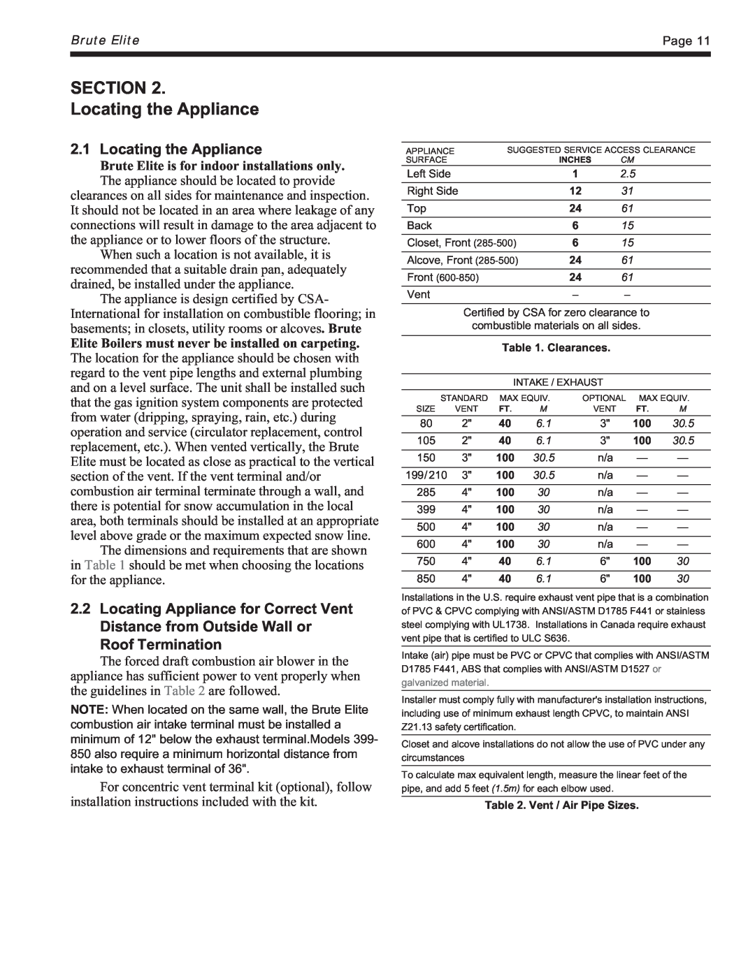
2.1 Locating the Appliance
Brute Elite is for indoor installations only
SECTION Locating the Appliance
3.1.2 Ducted Combustion Air
SECTION Venting and Combustion Air
3.1 Combustion Air
3.1.1 Combustion Air From Room
Table 5. Required Exhaust Vent Material
3.2 Venting
Figure 10. Combustion Air and Vent Through Roof
E. CPVC exhaust pipe section 80-500 not incl
3.3 Locating Vent & Combustion Air Terminals
3.2.1 Venting Requirements Unique to Canada
A. exhaust vent terminal not included
3.3.3 Vertical Vent Terminal
3.3.5 Installations in the Commonwealth of Massachusetts
3.3.2 Side Wall Combustion Air Terminal
5. For concentric vent, follow instructions included with vent kit
Figure 12. Combustion Air and Vent Through Side Wall
4. Inspection
3.4 Common Vent Test
2. Approved Carbon Monoxide Detectors
3. Signage
3. Refer to Tables 6A, 6B, 6C and 6D to size piping
SECTION Gas Supply and Piping
4.1 Gas Supply and Piping
Table 6A
SECTION Pump Requirements
5.1 Brute Elite Boiler Flow and Head Requirements see Table
5.2 Brute Elite Water Heater Flow and Head Requirements see Table
6A.2 BNTH Cold Water Make-Up
SECTION 6A Water Connections - BNTH Boiler
6A.1 BNTH System Piping Hot Supply Connections
1. Sentinel Performance Solutions Group 2. Hercules Chemical Company
6A.4 BNTH Suggested Piping Schematics
6A.3 Freeze Protection
6A.5 Recognized Chemicals
Figure 15. Hydronic Piping - Single Boiler zoning with circulators
Page
Figure 17. Hydronic Piping - Multiple Boilers zoning with circulators
Page
Brute Elite
Page
Page
Brute Elite
Page
Water Connections - BNTV Water Heater
SECTION 6B
6B.1 BNTV Water Quality
6B.2 Piping Requirements
6B.6 BNTV Suggested Pumps
6B.5 BNTV Suggested Piping Schematics
6B.3 Cold Water Make-Up
6B.4 Freeze Protection
water hardness at job site
Figure 25. DHW Piping, Two Heaters, One Vertical Tank
Figure 26. DHW Piping, Two Heaters, Two Vertical Tanks
Caution Pump sizing must be based opon
SECTION Electrical Connections
7.1 Main Power
7.4 Hydronic Call for Heat
7.10 Lead Lag/ Cascading Wiring Connections
7.2 Pump Connections
7.3 24Vac Transformer with Integral Circuit Breaker
Figure 28. Lead-Lag / Cascading Wiring Connections
Figure 29. Ladder Diagram
7.11 Wiring Diagrams see Figures 29 and
Figure 30. Wiring Diagram all sizes
8.2 Ignition Control- Sequence of Events
SECTION Brute Elite Control Setup and Operation
8.1 Display Navigation
8.7 Outlet Water Temperature
8.3 Modulation Control
8.5 Anti-Short Cycle ASC
8.5 High Limit
8.12.2 Lead Lag Master/Slave Selection
8.12.5 Lead Lag Base Load Setting
8.13 Boiler Pump Interrupt
8.12.1 Lead Lag Setpoint
9.1 Hydronic Heating Demand
9.2 Hydronic Heating with Outdoor Reset
9.4 Hydronic Heating Using External Modulation Control
SECTION Modes of Operation
Let’s consider the following example
9.5 Hydronic Heating Using Local Lead- Lag/Cascading Feature
9.7 Warm Weather Shutdown
9.8 Domestic Hot Water Demand BNTV only
9.9 Domestic Hot Water Heating Using External Modulation Control
10.2.1 Burner Operation
10.2 Operating the Burner and Set Up
SECTION Operating Instructions
10.1 Filling the Boiler System
3. WAIT FIVE 5 MINUTES
10.2.2 Boiler Setup and Adjustment
10.3 Shutting Down Brute Elite
10.4 To Restart Brute Elite
Figure 33B. Brute Elite Gas Valves 600, 750 and
80-285
Figure 33A. Brute Elite Gas Valves 285, 399 and
yearly, unless otherwise noted
SECTION Maintenance
11.1 System Maintenance
11.2 Appliance Maintenance and Component Description
Igniters and sensors get hot and can cause burns or injury
11.2.4 Ignitor Assembly
11.2.5 Flame Sensor
11.2.8 Heat Exchanger Coils
11.2.6 Transformer with Integral Circuit Breaker
11.2.7 Blower
12.1 Sequence of Operation
SECTION Trouble Shooting
12.3 Error Codes - See Table
11.2.9 Gas Pressure Switches optional
CODE#
PROBLEM
SOLUTION
continued next page
see Section
Table 18. Error Codes
Jacket Components - See Figure
SECTION Replacement Parts
13.2 Parts List
13.1 General Information
Gas Train Components - See Figure
Heat Exchanger Components - See Figure
Electrical Components - See Figure
Contact Customer Service at 800 900-9275
Figure 35. Jacket Components
Figure 36B. Internal Components, Sizes
Figure 36A. Internal Components, Sizes
Figure 36C. Internal Components, Sizes
Figure 37A. Gas Train Components, Sizes
Figure 37B. Gas Train Components, Sizes
Figure 38. Heat Exchanger Components
Figure 39. Electrical Components
Page
Ambler, PA
Tech. Service 800
Service Parts 800
Warranty Service 800