|
| RAMP INSTALLATION | |||
|
| ||||
|
|
|
|
|
|
Electrical Connections |
|
|
|
|
|
The 2 pin power harness connec- | Terminate the power supply, |
|
|
|
|
|
| WARNING |
| ||
tor and the | ground and ramp data signals as |
|
|
| |
connector are supplied with the | specified in the legends below. |
|
|
|
|
|
| Positive (+) battery |
| ||
ramp. |
|
|
|
| |
Note: Connectors are supplied | The Positive (+) “battery” lead |
|
| lead wire must be |
|
wire must be protected by an |
|
| protected by |
| |
only, harnesses are supplied by |
|
|
|
| |
ramp installer. The ramp installer | breaker (installer provided). |
|
| ampere fuse or |
|
is responsible for vehicle connec- |
|
|
| circuit breaker. |
|
tions. |
|
|
| Failure to do so may |
|
|
|
|
| result in serious |
|
The ramp installer provides an |
|
|
| bodily injury and/or |
|
appropriate momentary contact |
|
|
| property damage. |
|
control switch. |
|
|
|
|
|
|
|
|
|
| |
|
|
|
|
| |
Power Harness with Molex
Function | Pin No. | Description | Wire Size |
Input | 1 | Battery - 24 Volt with 25 Amp. Protection Device | 10 Gauge |
Input | 2 | Ground - Battery | 10 Gauge |
Wire Maximum Length: 10 Meters
Data Harness with AMP 206044-1 Connector (installer provided)
Function | Pin No. | Description | Wire Size |
Output | 1 | Indicator - Move Out - Normally Open (N.O.) | 14 to 18 Gauge |
Output | 2 | Indicator - Alarm - Normally Open (N.O.) | 14 to 18 Gauge |
Input | 3 | Switch - Ramp Deploy | 14 to 18 Gauge |
Input | 4 | Switch - One Touch | 14 to 18 Gauge |
Input | 5 | Indicator - Power Common Fused | 14 to 18 Gauge |
Output | 6 | Indicator - Manual Release - Normally Open (N.O.) | 14 to 18 Gauge |
Input | 7 | Ramp Enable | 14 to 18 Gauge |
Output | 8 | Switch - Common | 14 to 18 Gauge |
Output | 9 | Indicator - Full In - Normally Open (N.O.) | 14 to 18 Gauge |
Input | 10 | Switch - Ramp Stow | 14 to 18 Gauge |
Input | 11 | Switch - Park Brake (LOW) to Operate | 14 to 18 Gauge |
Output | 12 | Indicator - Move In - Normally Open (N.O.) | 14 to 18 Gauge |
Output | 13 | Indicator - Full Out - Normally Open (N.O.) | 14 to 18 Gauge |
Input | 14 | Switch - Park Brake (HIGH) to Operate | 14 to 18 Gauge |
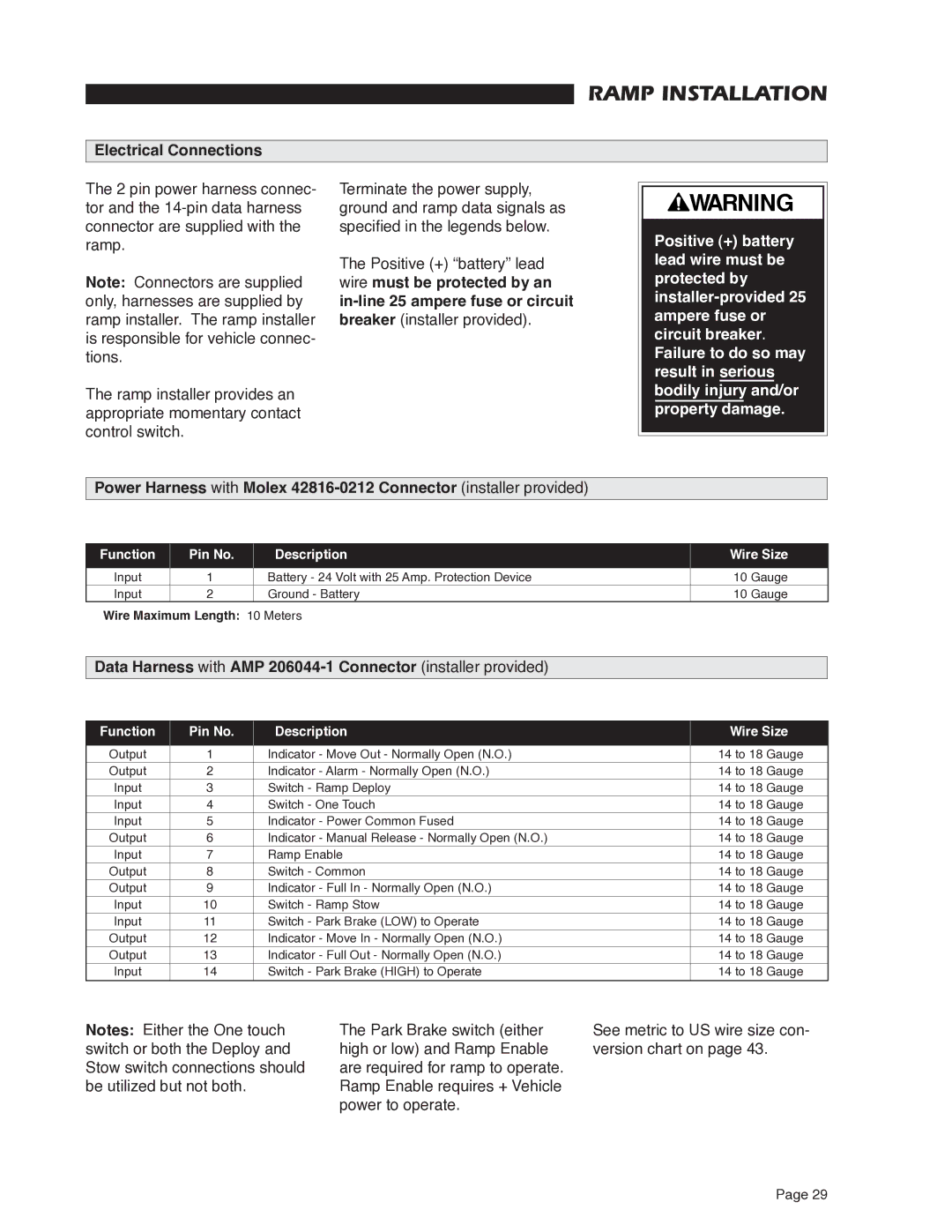
Notes: Either the One touch switch or both the Deploy and Stow switch connections should be utilized but not both.
The Park Brake switch (either high or low) and Ramp Enable are required for ramp to operate. Ramp Enable requires + Vehicle power to operate.
See metric to US wire size con- version chart on page 43.
Page 29
