SYSTEMS DESCRIPTIONS
Manual Calibration Instructions for Controller
Press the “Calibrate” button. Once pressed, the calibrate LED should turn on.
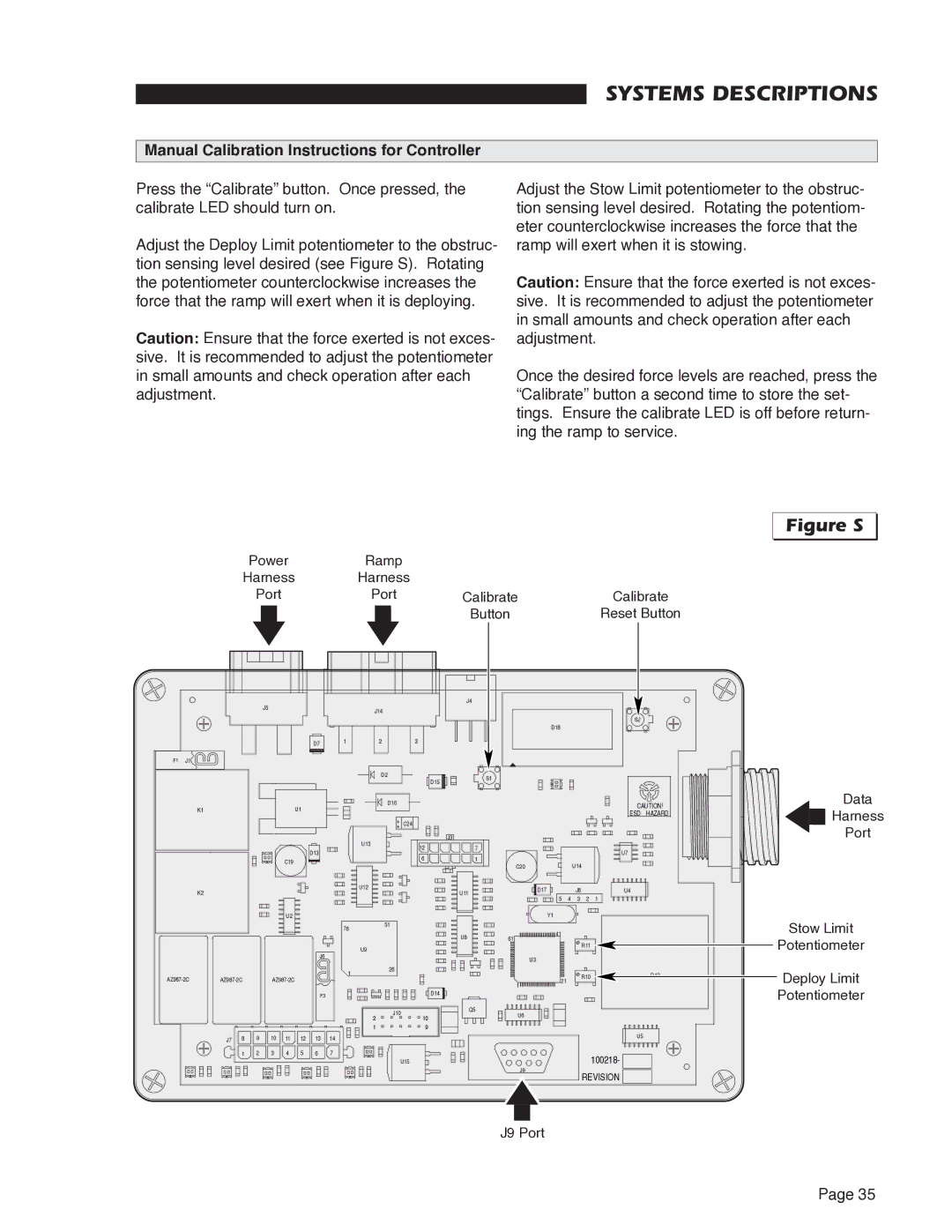
Adjust the Deploy Limit potentiometer to the obstruc- tion sensing level desired (see Figure S). Rotating the potentiometer counterclockwise increases the force that the ramp will exert when it is deploying.
Caution: Ensure that the force exerted is not exces- sive. It is recommended to adjust the potentiometer in small amounts and check operation after each adjustment.
Adjust the Stow Limit potentiometer to the obstruc- tion sensing level desired. Rotating the potentiom- eter counterclockwise increases the force that the ramp will exert when it is stowing.
Caution: Ensure that the force exerted is not exces- sive. It is recommended to adjust the potentiometer in small amounts and check operation after each adjustment.
Once the desired force levels are reached, press the “Calibrate” button a second time to store the set- tings. Ensure the calibrate LED is off before return- ing the ramp to service.
|
|
|
| Power |
|
|
| Ramp |
|
|
|
|
|
|
|
|
|
| |||
|
|
| Harness |
|
|
| Harness |
|
|
|
|
|
|
|
|
| |||||
|
|
|
| Port |
|
|
|
| Port |
| Calibrate |
|
|
|
| Calibrate | |||||
|
|
|
|
|
|
|
|
|
|
|
|
|
| Button |
|
|
|
|
| Reset Button | |
|
|
|
|
| J5 |
|
|
|
|
|
|
| J4 |
|
|
|
|
|
|
| |
|
|
|
|
|
|
|
|
| J14 |
|
|
|
|
|
|
|
|
|
| ||
|
|
|
|
|
|
|
|
|
|
|
|
|
|
|
|
|
|
|
| ||
|
|
|
|
|
|
|
|
|
|
|
|
|
|
|
| D18 |
|
|
|
|
|
|
|
|
|
|
|
|
| D7 | 1 |
| 2 |
| 3 |
|
|
|
|
|
|
|
|
F1 | J1 |
|
|
|
|
|
|
|
|
|
|
|
|
|
|
|
|
|
|
|
|
|
|
|
|
|
|
|
|
|
|
| D2 |
| D15 | S1 |
|
|
|
|
|
|
|
|
|
|
|
|
|
|
|
|
|
|
|
|
|
|
|
|
|
|
| ||
|
|
|
|
|
|
|
|
|
|
|
|
|
|
|
|
|
|
|
|
| |
|
| K1 |
|
|
|
| U1 |
|
|
| D16 |
|
|
|
|
|
|
|
| CAUTION! | |
|
|
|
|
|
|
|
|
|
|
|
|
|
|
|
|
|
| ESD | HAZARD | ||
|
|
|
|
|
|
|
|
|
|
| ++ |
|
|
|
|
|
|
|
| ||
|
|
|
|
|
|
|
|
|
|
| C24 |
|
|
|
|
|
|
|
|
| |
|
|
|
|
|
|
|
|
|
| U13 |
|
| J3 |
|
|
|
|
|
|
|
|
|
|
|
|
|
|
|
| D13 |
|
|
| 12 | 7 |
|
|
|
|
| U7 |
| |
|
|
|
|
|
|
|
|
|
|
|
|
|
|
|
|
|
| ||||
|
|
|
|
|
| C19 |
|
|
|
|
| 6 | 1 |
|
|
|
|
|
| ||
|
|
|
|
|
|
|
|
|
|
|
| C20 |
|
| U14 |
|
|
| |||
|
|
|
|
|
|
|
|
|
|
|
|
|
|
|
|
|
|
| |||
|
|
|
|
|
|
|
|
|
|
|
|
|
|
|
|
|
|
|
| ||
|
| K2 |
|
|
|
|
|
|
| U12 |
|
| U11 |
|
| D17 |
| J8 |
| U4 |
|
|
|
|
|
|
|
|
|
|
|
|
|
|
| 4 | 2 |
| |||||
|
|
|
|
|
|
|
|
|
|
|
|
|
|
|
| 5 | 3 | 1 |
| ||
|
|
|
|
|
| U2 |
|
|
|
| 51 |
|
|
|
| Y1 |
|
|
|
|
|
|
|
|
|
|
|
|
|
| 76 |
|
|
|
|
| 41 |
|
|
|
|
| |
|
|
|
|
|
|
|
|
|
|
|
| U8 |
|
|
|
|
|
|
| ||
|
|
|
|
|
|
|
|
|
|
|
|
| 61 |
|
|
|
|
|
| ||
|
|
|
|
|
|
|
|
|
|
|
|
|
|
|
|
| R11 |
|
| ||
|
|
|
|
|
|
|
|
|
| U9 |
|
|
|
|
|
|
|
|
|
| |
|
|
|
|
|
|
|
| J6 |
|
|
|
|
|
|
|
|
|
|
|
| |
|
|
|
|
|
|
|
|
|
|
|
|
|
|
| U3 |
|
|
|
|
| |
|
|
|
|
|
|
|
|
|
|
| 26 |
|
|
|
|
|
|
|
|
| |
|
|
|
|
|
|
|
|
| 1 |
|
|
|
|
|
|
|
| R10 |
| D12 | |
|
|
|
|
|
|
|
| 1 | 21 |
|
|
| |||||||||
|
|
|
|
|
|
|
|
|
|
|
|
|
| ||||||||
|
|
|
|
|
|
|
|
|
|
|
|
| D14 |
|
|
|
|
|
|
| |
|
|
|
|
|
|
|
| F3 |
|
|
|
|
|
|
|
|
|
|
|
| |
|
|
|
|
|
|
|
|
|
| 2 | J10 |
| 10 | Q5 | U6 |
|
|
|
|
|
|
|
|
|
|
|
|
|
|
|
|
|
|
|
|
|
|
|
| ||||
|
|
|
|
|
|
|
|
|
|
|
|
|
|
|
|
|
|
|
| ||
|
|
|
|
|
|
|
|
|
| 1 |
|
| 9 |
|
|
|
|
|
| U5 |
|
|
| J7 | 8 | 9 | 10 | 11 | 12 | 13 | 14 |
|
|
|
|
|
|
|
|
|
|
| |
|
|
| 1 | 2 | 3 | 4 | 5 | 6 | 7 |
| U15 |
|
|
|
|
|
|
| 100218- |
| |
|
|
|
|
|
|
|
|
|
|
|
|
| J9 |
|
|
|
|
| |||
|
|
|
|
|
|
|
|
|
|
|
|
|
|
|
|
|
| REVISION |
| ||
|
|
|
|
|
|
|
|
|
|
|
|
|
|
|
|
|
|
|
| ||
J9 Port
Figure S
Data
Harness
Port
Stow Limit
Potentiometer
Deploy Limit
Potentiometer
Page 35