RAMP INSTALLATION 
Electrical Connections
The ramp installer provides an | Installer connections are listed in |
|
|
|
| WARNING |
| ||
appropriate control switch for the | the table on the following page. |
|
| |
end user. | Strip wires, crimp and install con- |
|
|
|
Route cables clear |
| |||
using a single "operate" button | tacts as specified in instructions |
|
| |
(switch) or | supplied with the power connec- |
| of exhaust system, |
|
tion with dedicated switches for | tor (Molex |
| other hot areas and |
|
the stow and deploy command | connector (Amp |
| moving parts. Failure |
|
are options. |
|
| to do so may result |
|
|
|
| in serious bodily |
|
|
|
| injury and/or property |
|
|
|
| damage. |
|
|
|
|
|
|
|
|
|
|
|
Battery / Ground Connections
The Positive (+) “battery” lead wire must be protected by an
Do not connect the power “battery” lead wire to the battery until all other connec- tions are made.
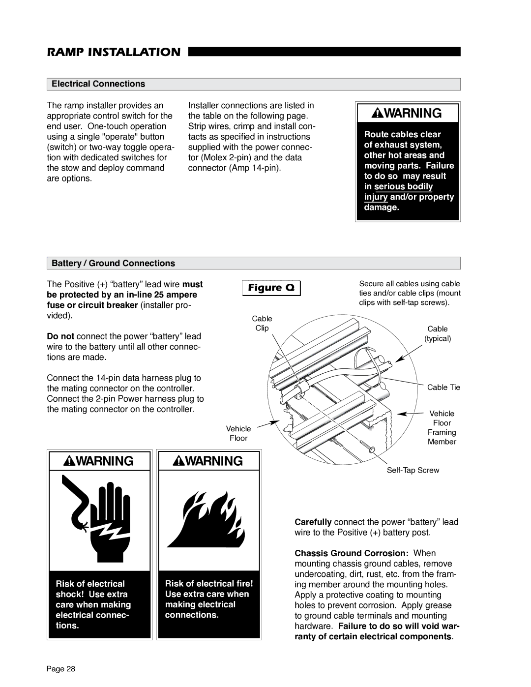
Figure Q 

Cable
Clip
Secure all cables using cable ties and/or cable clips (mount clips with
Cable
(typical)
Connect the
Vehicle
Floor
WARNING |
| WARNING | ||
|
|
|
|
|
|
|
|
|
|
|
|
|
|
|
|
|
|
|
|
|
|
|
|
|
Risk of electrical | Risk of electrical fire! |
shock! Use extra | Use extra care when |
care when making | making electrical |
electrical connec- | connections. |
tions. |
|
Cable Tie
![]() Vehicle
Vehicle
Floor
Framing
Member
Carefully connect the power “battery” lead wire to the Positive (+) battery post.
Chassis Ground Corrosion: When mounting chassis ground cables, remove undercoating, dirt, rust, etc. from the fram- ing member around the mounting holes. Apply a protective coating to mounting holes to prevent corrosion. Apply grease to ground cable terminals and mounting hardware. Failure to do so will void war- ranty of certain electrical components.
Page 28