SYSTEMS DESCRIPTIONS
Computer Calibration Instructions for Controller (continued)
Calibrate the Controller:
Press the “Calibrate” button on the controller (see Figure S). Ensure that the Calibrate LED is red. If connected properly, a text window will pop up. The numerical values will be different, but the general format of the text window will read similar to the fol- lowing:
Deploy Limit: 50 | Stow Limit: 975 |
Adjust limits as follows: |
|
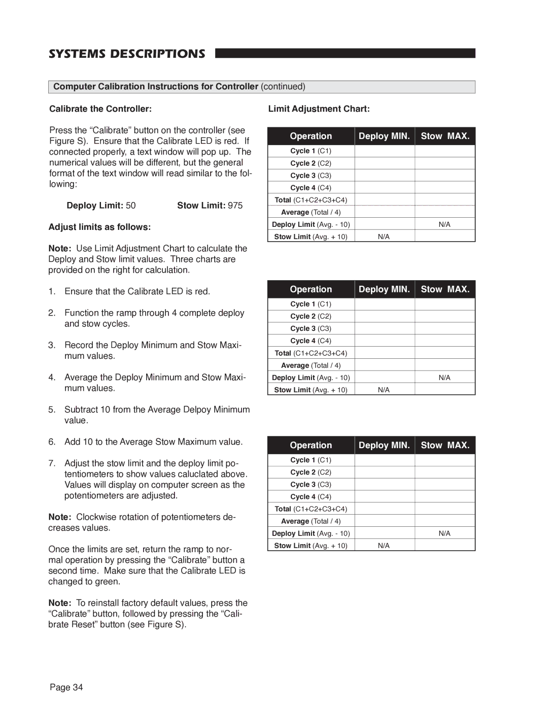
Note: Use Limit Adjustment Chart to calculate the Deploy and Stow limit values. Three charts are provided on the right for calculation.
1.Ensure that the Calibrate LED is red.
2.Function the ramp through 4 complete deploy and stow cycles.
3.Record the Deploy Minimum and Stow Maxi- mum values.
4.Average the Deploy Minimum and Stow Maxi- mum values.
5.Subtract 10 from the Average Delpoy Minimum value.
6.Add 10 to the Average Stow Maximum value.
7.Adjust the stow limit and the deploy limit po- tentiometers to show values caluclated above. Values will display on computer screen as the potentiometers are adjusted.
Note: Clockwise rotation of potentiometers de- creases values.
Once the limits are set, return the ramp to nor- mal operation by pressing the “Calibrate” button a second time. Make sure that the Calibrate LED is changed to green.
Note: To reinstall factory default values, press the “Calibrate” button, followed by pressing the “Cali- brate Reset” button (see Figure S).
Limit Adjustment Chart:
Operation | Deploy MIN. Stow MAX. | |
Cycle 1 (C1) |
|
|
Cycle 2 (C2) |
|
|
Cycle 3 (C3) |
|
|
Cycle 4 (C4) |
|
|
Total (C1+C2+C3+C4) |
|
|
Average (Total / 4) |
|
|
Deploy Limit (Avg. - 10) |
| N/A |
Stow Limit (Avg. + 10) | N/A |
|
Operation | Deploy MIN. Stow MAX. | |
Cycle 1 (C1) |
|
|
Cycle 2 (C2) |
|
|
Cycle 3 (C3) |
|
|
Cycle 4 (C4) |
|
|
Total (C1+C2+C3+C4) |
|
|
Average (Total / 4) |
|
|
Deploy Limit (Avg. - 10) |
| N/A |
Stow Limit (Avg. + 10) | N/A |
|
Operation | Deploy MIN. Stow MAX. | |
Cycle 1 (C1) |
|
|
Cycle 2 (C2) |
|
|
Cycle 3 (C3) |
|
|
Cycle 4 (C4) |
|
|
Total (C1+C2+C3+C4) |
|
|
Average (Total / 4) |
|
|
Deploy Limit (Avg. - 10) |
| N/A |
Stow Limit (Avg. + 10) | N/A |
|
Page 34