Bryant 581B installation instructions Ð Specications

Models: 581B

1 40
Download 40 pages 47.12 Kb
Page 6
Image 6

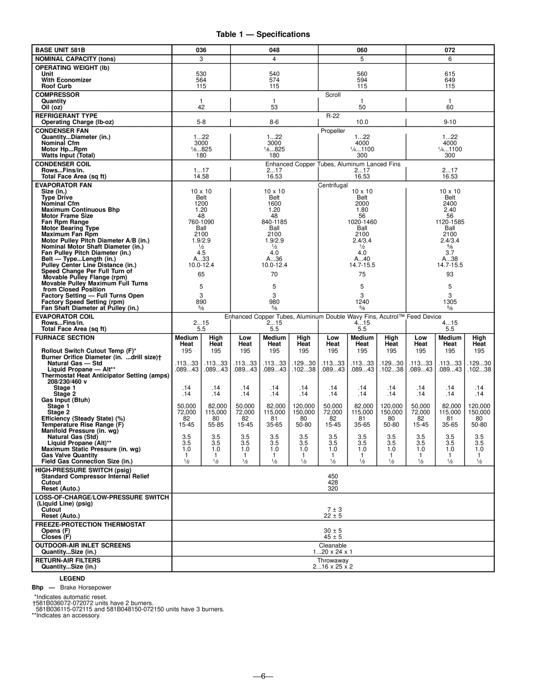
Table 1 Ð Speci®cations

BASE UNIT 581B

036


048


060


072


NOMINAL CAPACITY (tons)


3


4


5


6


OPERATING WEIGHT (lb)


Unit

530


540


560


615


With Economizer

564


574


594


649


Roof Curb

115


115


115


115


COMPRESSOR


Scroll


Quantity


1


1


1


1


Oil (oz)

42


53


50


60


REFRIGERANT TYPE


R-22


Operating Charge (lb-oz)

5-8


8-6


10.0


9-10


CONDENSER FAN


Propeller


Quantity...Diameter (in.)

1...22


1...22


1...22


1...22


Nominal Cfm

3000


3000


4000


4000


Motor Hp...Rpm

1¤8...825


1¤8...825


1¤4...1100


1¤4...1100


Watts Input (Total)

180


180


300


300


CONDENSER COIL


Enhanced Copper Tubes, Aluminum Lanced Fins


Rows...Fins/in.

1...17


2...17


2...17


2...17


Total Face Area (sq ft)

14.58


16.53


16.53


16.53


EVAPORATOR FAN


Centrifugal


Size (in.)

10 x 10


10 x 10


10 x 10


10 x 10


Type Drive

Belt


Belt


Belt


Belt


Nominal Cfm

1200


1600


2000


2400


Maximum Continuous Bhp

1.20


1.20


1.80


2.40


Motor Frame Size

48


48


56


56


Fan Rpm Range

760-1090


840-1185


1020-1460


1120-1585


Motor Bearing Type

Ball


Ball


Ball


Ball


Maximum Fan Rpm

2100


2100


2100


2100


Motor Pulley Pitch Diameter A/B (in.)

1.9/2.9


1.9/2.9


2.4/3.4


2.4/3.4


Nominal Motor Shaft Diameter (in.)

1¤2


1¤2


1¤2


5¤8


Fan Pulley Pitch Diameter (in.)

4.5


4.0


4.0


3.7


Belt Ð Type...Length (in.)

A...33


A...36


A...40


A...38


Pulley Center Line Distance (in.)

10.0-12.4


10.0-12.4


14.7-15.5


14.7-15.5


Speed Change Per Full Turn of

65


70


75


93


Movable Pulley Flange (rpm)


Movable Pulley Maximum Full Turns


5


5


5


5


from Closed Position


Factory Setting Ð Full Turns Open


3


3


3


3


Factory Speed Setting (rpm)

890


980


1240


1305


Fan Shaft Diameter at Pulley (in.)

5¤8


5¤8


5¤8


5¤8


EVAPORATOR COIL


Enhanced Copper Tubes, Aluminum Double Wavy Fins, Acutrol™ Feed Device


Rows...Fins/in.

2...15


2...15


4...15


4...15


Total Face Area (sq ft)

5.5


5.5


5.5


5.5


FURNACE SECTION

Medium


High

Low

Medium

High

Low

Medium

High

Low

Medium

High

Rollout Switch Cutout Temp (F)*

Heat


Heat

Heat

Heat

Heat

Heat

Heat

Heat

Heat

Heat

Heat

195


195

195

195

195

195

195

195

195

195

195

Burner Ori®ce Diameter (in. ...drill size)²


Natural Gas Ð Std

.113...33

.113...33

.113...33

.113...33

.129...30

.113...33

.113...33

.129...30

.113...33

.113...33

.129...30

Liquid Propane Ð Alt**

.089...43


.089...43

.089...43

.089...43

.102...38

.089...43

.089...43

.102...38

.089...43

.089...43

.102...38

Thermostat Heat Anticipator Setting (amps)


208/230/460 v


Stage 1

.14


.14

.14

.14

.14

.14

.14

.14

.14

.14

.14

Stage 2

.14


.14

.14

.14

.14

.14

.14

.14

.14

.14

.14

Gas Input (Btuh)


Stage 1

50,000


82,000

50,000

82,000

120,000

50,000

82,000

120,000

50,000

82,000

120,000

Stage 2

72,000


115,000

72,000

115,000

150,000

72,000

115,000

150,000

72,000

115,000

150,000

Efficiency (Steady State) (%)

82


80

82

81

80

82

81

80

82

81

80

Temperature Rise Range (F)

15-45


55-85

15-45

35-65

50-80

15-45

35-65

50-80

15-45

35-65

50-80

Manifold Pressure (in. wg)


Natural Gas (Std)

3.5


3.5

3.5

3.5

3.5

3.5

3.5

3.5

3.5

3.5

3.5

Liquid Propane (Alt)**

3.5


3.5

3.5

3.5

3.5

3.5

3.5

3.5

3.5

3.5

3.5

Maximum Static Pressure (in. wg)

1.0


1.0

1.0

1.0

1.0

1.0

1.0

1.0

1.0

1.0

1.0

Gas Valve Quantity

1


1

1

1

1

1

1

1

1

1

1

Field Gas Connection Size (in.)

1¤2


1¤2

1¤2

1¤2

1¤2

1¤2

1¤2

1¤2

1¤2

1¤2

1¤2

HIGH-PRESSURE SWITCH (psig)


Standard Compressor Internal Relief


450


Cutout


428


Reset (Auto.)


320


LOSS-OF-CHARGE/LOW-PRESSURE SWITCH


(Liquid Line) (psig)


Cutout


7 ± 3


Reset (Auto.)


22 ± 5


FREEZE-PROTECTION THERMOSTAT


Opens (F)


30 ± 5


Closes (F)


45 ± 5


OUTDOOR-AIR INLET SCREENS


Cleanable


Quantity...Size (in.)


1...20 x 24 x 1


RETURN-AIR FILTERS


Throwaway


Quantity...Size (in.)


2...16 x 25 x 2


LEGEND

Bhp Ð Brake Horsepower

*Indicates automatic reset. ²581B036072-072072 units have 2 burners.

581B036115-072115 and 581B048150-072150 units have 3 burners. **Indicates an accessory.

Ð6Ð

Page 6
Image 6
Bryant 581B installation instructions Ð Specications