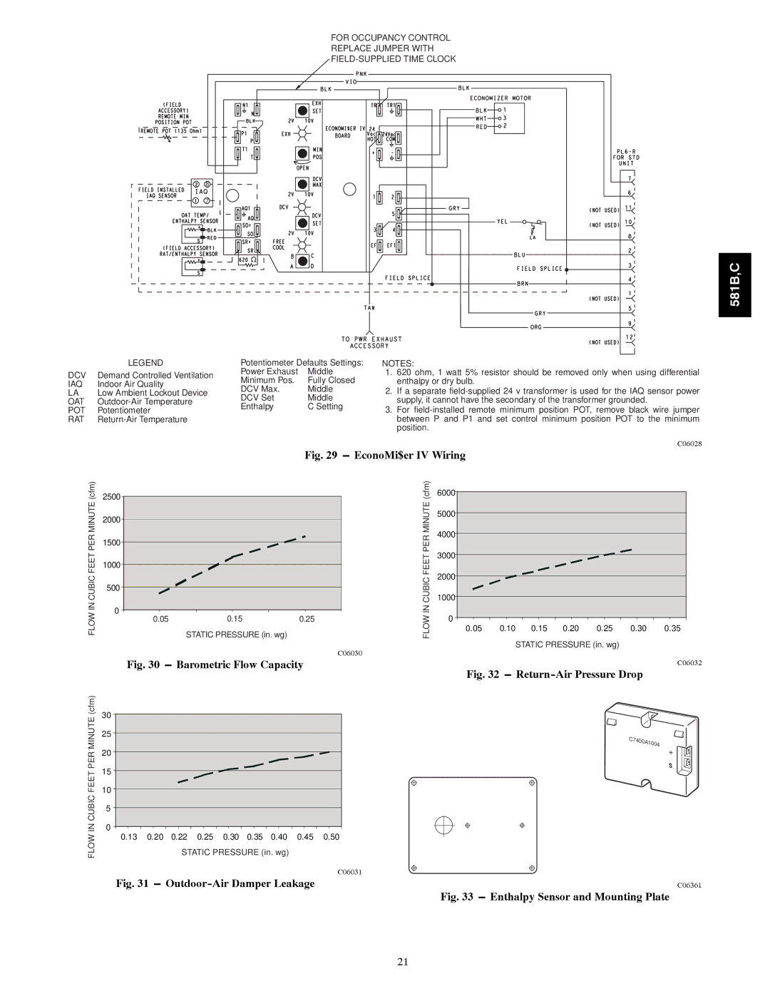
FOR OCCUPANCY CONTROL
REPLACE JUMPER WITH
8
7
581B,C
LEGEND | Potentiometer Defaults Settings: | ||
DCV— Demand Controlled Ventilation | Power Exhaust | Middle | |
Minimum Pos. | Fully Closed | ||
IAQ — Indoor Air Quality | |||
DCV Max. | Middle | ||
LA — Low Ambient Lockout Device | |||
DCV Set | Middle | ||
OAT — | |||
Enthalpy | C Setting | ||
POT — Potentiometer | |||
|
| ||
RAT —
NOTES:
1.620 ohm, 1 watt 5% resistor should be removed only when using differential enthalpy or dry bulb.
2.If a separate
3.For
Fig. 29 --- EconoMi$er IV Wiring
(cfm) | 2500 |
|
|
|
| (cfm) | 6000 |
|
|
|
|
|
|
|
|
|
|
|
|
|
|
|
| ||||
MINUTE | 2000 |
|
|
|
| MINUTE | 5000 |
|
|
|
|
|
|
PER |
|
|
|
| PER | 4000 |
|
|
|
|
|
| |
1500 |
|
|
|
|
|
|
|
|
|
| |||
|
|
|
| 3000 |
|
|
|
|
|
| |||
FEET |
|
|
|
| FEET |
|
|
|
|
|
| ||
1000 |
|
|
|
|
|
|
|
|
|
| |||
|
|
|
| 2000 |
|
|
|
|
|
| |||
CUBICINFLOW |
|
| STATIC PRESSURE (in. wg) |
| CUBICINFLOW |
|
|
|
|
|
| ||
|
|
|
|
|
|
|
|
|
| ||||
500 |
|
|
| 1000 |
|
|
|
|
|
| |||
|
|
|
|
|
|
|
|
|
|
|
| ||
|
|
|
|
|
|
|
|
|
|
|
|
| |
| 0 |
|
|
|
|
| 0 |
|
|
|
|
|
|
|
| 0.05 | 0.15 | 0.25 |
|
|
|
|
|
|
| ||
|
|
|
|
|
|
|
| ||||||
|
|
|
|
|
|
| 0.05 | 0.10 | 0.15 | 0.20 | 0.25 | 0.30 | |
STATIC PRESSURE (in. wg)
C06030
Fig. 30 --- Barometric Flow Capacity
Fig. 32 --- Return-Air Pressure Drop
C06028
0.35
C06032
FLOW IN CUBIC FEET PER MINUTE (cfm)
30
25
20
15
10
5
0
0.130.20 0.22 0.25 0.30 0.35 0.40 0.45 0.50 STATIC PRESSURE (in. wg)
C06031
Fig. 31 --- Outdoor-Air Damper Leakage
HH57AC078 ENTHALPY |
|
SENSOR | C7400A1004 |
| |
| + |
MOUNTING PLATE
C06361
Fig. 33 --- Enthalpy Sensor and Mounting Plate
21