581B,C
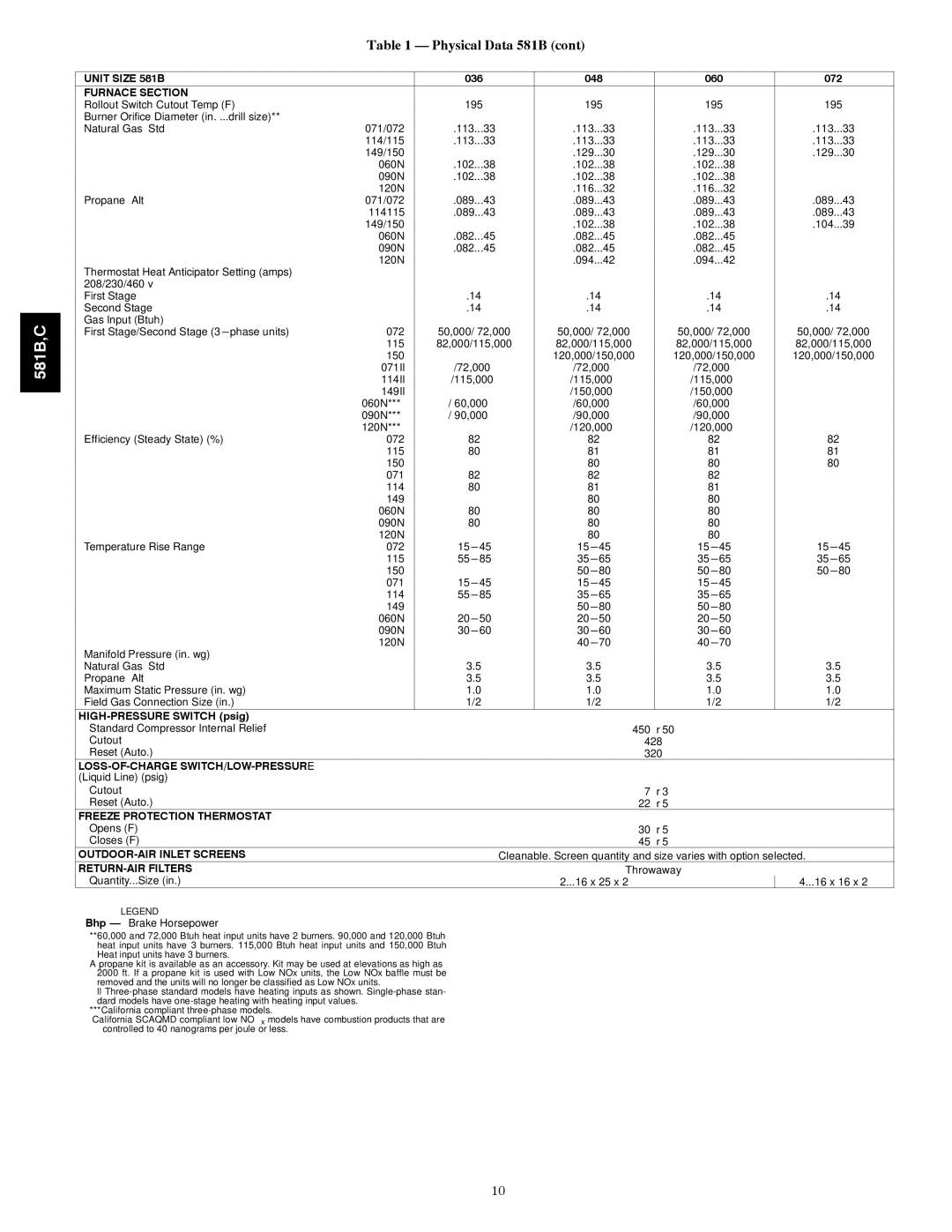
Table 1 — Physical Data 581B (cont)
UNIT SIZE 581B |
|
| 036 | 048 | 060 | 072 | ||||
FURNACE SECTION |
|
|
|
|
|
|
|
|
|
|
Rollout Switch Cutout Temp (F)† |
| 195 | 195 | 195 | 195 | |||||
Burner Orifice Diameter (in. ... | drill size)** |
|
|
|
|
|
|
|
|
|
Natural Gas |
| 071/072 | .113 | ...33 | .113 | ...33 | .113 | ...33 | .113 | ...33 |
|
| 114/115 | .113 | ...33 | .113 | ...33 | .113 | ...33 | .113 | ...33 |
|
| 149/150 | — | .129 | ...30 | .129 | ...30 | .129 | ...30 | |
|
| 060N | .102 | ...38 | .102 | ...38 | .102 | ...38 | — | |
|
| 090N | .102 | ...38 | .102 | ...38 | .102 | ...38 | — | |
|
| 120N | — | .116 | ...32 | .116 | ...32 | — | ||
Propane |
| 071/072 | .089 | ...43 | .089 | ...43 | .089 | ...43 | .089 | ...43 |
|
| 114115 | .089 | ...43 | .089 | ...43 | .089 | ...43 | .089 | ...43 |
|
| 149/150 | — | .102 | ...38 | .102 | ...38 | .104 | ...39 | |
|
| 060N | .082 | ...45 | .082 | ...45 | .082 | ...45 | — | |
|
| 090N | .082 | ...45 | .082 | ...45 | .082 | ...45 | — | |
Thermostat Heat Anticipator Setting (amps) | 120N | — | .094 | ...42 | .094 | ...42 | — | |||
|
|
|
|
|
|
|
|
| ||
208/230/460 v |
|
|
|
|
|
|
|
|
|
|
First Stage |
|
| .14 | .14 | .14 | .14 | ||||
Second Stage |
|
| .14 | .14 | .14 | .14 | ||||
Gas Input (Btuh) |
|
|
|
|
|
|
|
|
|
|
First Stage/Second Stage | phase units) | 072 | 50,000/ 72,000 | 50,000/ 72,000 | 50,000/ 72,000 | 50,000/ 72,000 | ||||
|
| 115 | 82,000/115,000 | 82,000/115,000 | 82,000/115,000 | 82,000/115,000 | ||||
|
| 150 | — | 120,000/150,000 | 120,000/150,000 | 120,000/150,000 | ||||
|
| 071II | — | |||||||
|
| 114II | — | |||||||
|
| 149II | — | — | ||||||
|
| 060N*** | — | |||||||
|
| 090N*** | — | |||||||
|
| 120N*** | — | — | ||||||
Efficiency (Steady State) (%) |
| 072 | 82 | 82 | 82 | 82 | ||||
|
| 115 | 80 | 81 | 81 | 81 | ||||
|
| 150 | — | 80 | 80 | 80 | ||||
|
| 071 | 82 | 82 | 82 | — | ||||
|
| 114 | 80 | 81 | 81 | — | ||||
|
| 149 | — | 80 | 80 | — | ||||
|
| 060N | 80 | 80 | 80 | — | ||||
|
| 090N | 80 | 80 | 80 | — | ||||
|
| 120N | — | 80 | 80 | — | ||||
Temperature Rise Range |
| 072 | 45 | 45 | 45 | 45 | ||||
|
| 115 | 85 | 65 | 65 | 65 | ||||
|
| 150 | — | 80 | 80 | 80 | ||||
|
| 071 | 45 | 45 | 45 | — | ||||
|
| 114 | 85 | 65 | 65 | — | ||||
|
| 149 | — | 80 | 80 | — | ||||
|
| 060N | 50 | 50 | 50 | — | ||||
|
| 090N | 60 | 60 | 60 | — | ||||
Manifold Pressure (in. wg) |
| 120N | — | 70 | 70 | — | ||||
|
|
|
|
|
|
|
|
|
| |
Natural Gas |
|
| 3.5 | 3.5 | 3.5 | 3.5 | ||||
Propane |
|
| 3.5 | 3.5 | 3.5 | 3.5 | ||||
Maximum Static Pressure (in. wg) |
| 1.0 | 1.0 | 1.0 | 1.0 | |||||
Field Gas Connection Size (in.) |
| 1/2 | 1/2 | 1/2 | 1/2 | |||||
|
|
|
| |
Standard Compressor Internal Relief | 450 | ± | 50 |
|
Cutout | 428 |
|
| |
Reset (Auto.) | 320 |
|
| |
|
|
|
| |
(Liquid Line) (psig) |
|
|
|
|
Cutout | 7 | ± | 3 |
|
Reset (Auto.) | 22 | ± | 5 |
|
FREEZE PROTECTION THERMOSTAT |
|
|
|
|
Opens (F) | 30 | ± | 5 |
|
Closes (F) | 45 | ± | 5 |
|
Cleanable. Screen quantity and size varies with option selected. | ||||
| Throwaway | |||
...Quantity Size (in.) | ...2 16 x 25 x 2 |
|
| ...4 16 x 16 x 2 |
LEGEND
Bhp — Brake Horsepower
**60,000 and 72,000 Btuh heat input units have 2 burners. 90,000 and 120,000 Btuh heat input units have 3 burners. 115,000 Btuh heat input units and 150,000 Btuh Heat input units have 3 burners.
††A propane kit is available as an accessory. Kit may be used at elevations as high as 2000 ft. If a propane kit is used with Low NOx units, the Low NOx baffle must be removed and the units will no longer be classified as Low NOx units.
ll
***California compliant
†††California SCAQMD compliant low NOx models have combustion products that are controlled to 40 nanograms per joule or less.
10