581B,C
C06142
Fig. 54 --- Cooling Charging Chart,
Standard 581B 072
C06143 |
Fig. 55 --- Cooling Charging Chart, 581B 036 with Optional Perfect Humidity Adaptive Dehumidification System
C06144 |
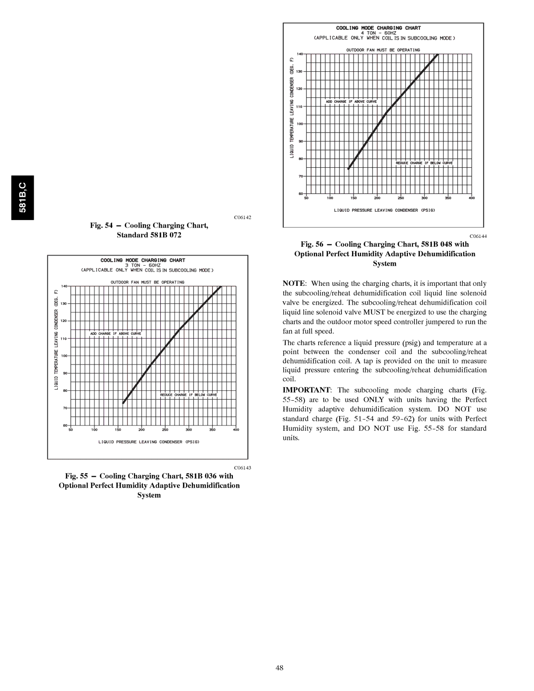
Fig. 56 --- Cooling Charging Chart, 581B 048 with Optional Perfect Humidity Adaptive Dehumidification System
NOTE: When using the charging charts, it is important that only the subcooling/reheat dehumidification coil liquid line solenoid valve be energized. The subcooling/reheat dehumidification coil liquid line solenoid valve MUST be energized to use the charging charts and the outdoor motor speed controller jumpered to run the fan at full speed.
The charts reference a liquid pressure (psig) and temperature at a point between the condenser coil and the subcooling/reheat dehumidification coil. A tap is provided on the unit to measure liquid pressure entering the subcooling/reheat dehumidification coil.
IMPORTANT: The subcooling mode charging charts (Fig.
48