NOTES:
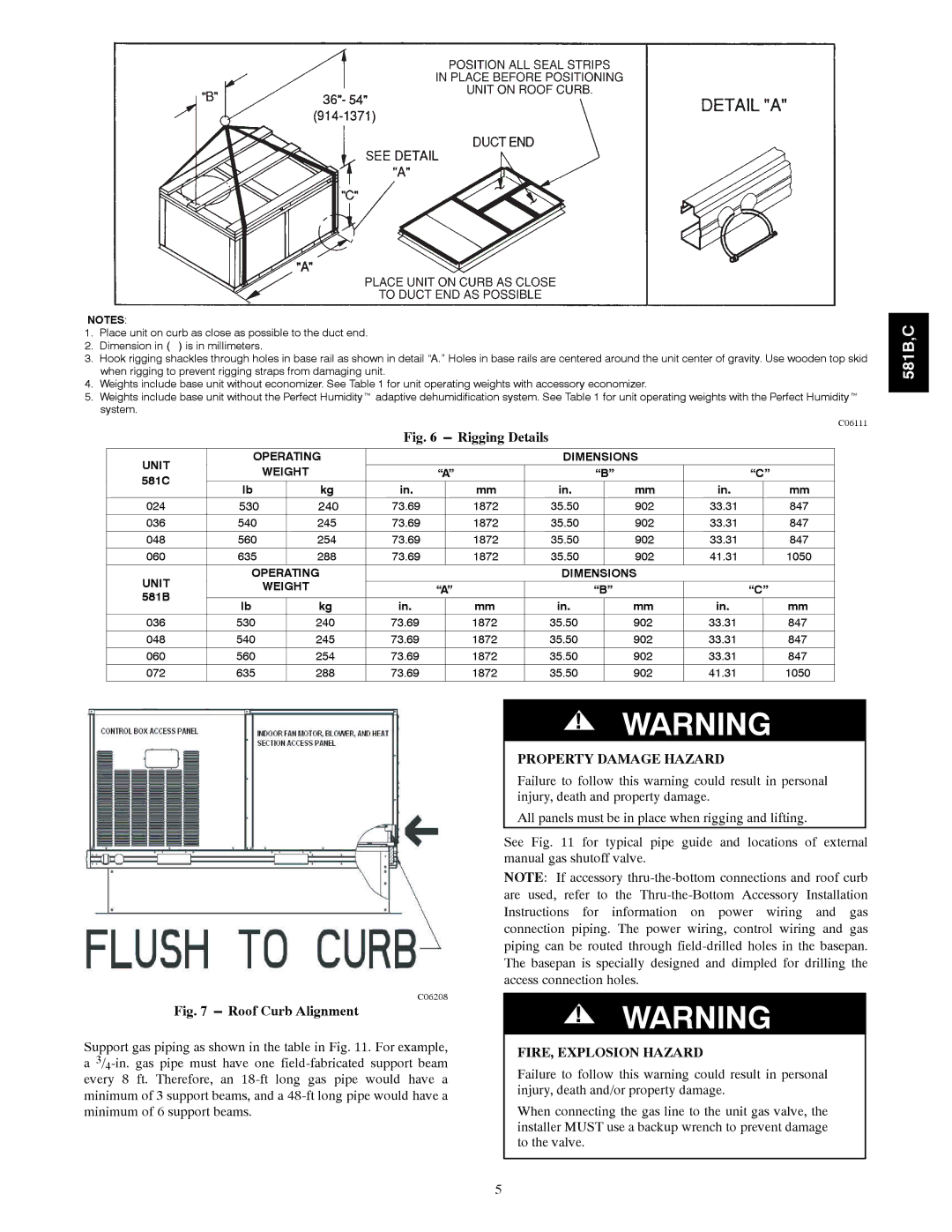
1. | Place unit on curb as close as possible to the duct end. |
2. | Dimension in ( ) is in millimeters. |
3.Hook rigging shackles through holes in base rail as shown in detail “A.” Holes in base rails are centered around the unit center of gravity. Use wooden top skid when rigging to prevent rigging straps from damaging unit.
4.Weights include base unit without economizer. See Table 1 for unit operating weights with accessory economizer.
5.Weights include base unit without the Perfect Humidityt adaptive dehumidification system. See Table 1 for unit operating weights with the Perfect Humidityt system.
C06111
|
|
|
| Fig. 6 | Rigging Details |
|
|
|
|
|
| ||
|
|
|
|
|
|
|
|
|
|
|
| ||
UNIT | OPERATING |
|
|
|
| DIMENSIONS |
|
|
| ||||
| WEIGHT | “A” |
|
|
| “B” |
| “C” | |||||
581C |
|
|
|
|
| ||||||||
lb |
| kg | in. |
| mm |
| in. |
| mm | in. |
| mm | |
|
|
|
|
|
| ||||||||
024 | 530 |
| 240 | 73.69 |
| 1872 |
| 35.50 |
| 902 | 33.31 |
| 847 |
036 | 540 |
| 245 | 73.69 |
| 1872 |
| 35.50 |
| 902 | 33.31 |
| 847 |
048 | 560 |
| 254 | 73.69 |
| 1872 |
| 35.50 |
| 902 | 33.31 |
| 847 |
060 | 635 |
| 288 | 73.69 |
| 1872 |
| 35.50 |
| 902 | 41.31 |
| 1050 |
UNIT | OPERATING |
|
|
|
| DIMENSIONS |
|
|
| ||||
| WEIGHT | “A” |
|
|
| “B” |
| “C” | |||||
581B |
|
|
|
|
|
|
|
|
|
|
|
|
|
lb |
| kg | in. |
| mm |
| in. |
| mm | in. |
| mm | |
|
|
|
|
|
| ||||||||
036 | 530 |
| 240 | 73.69 |
| 1872 |
| 35.50 |
| 902 | 33.31 |
| 847 |
048 | 540 |
| 245 | 73.69 |
| 1872 |
| 35.50 |
| 902 | 33.31 |
| 847 |
060 | 560 |
| 254 | 73.69 |
| 1872 |
| 35.50 |
| 902 | 33.31 |
| 847 |
072 | 635 |
| 288 | 73.69 |
| 1872 |
| 35.50 |
| 902 | 41.31 |
| 1050 |
581B,C
C06208
Fig. 7 --- Roof Curb Alignment
Support gas piping as shown in the table in Fig. 11. For example, a
!WARNING
PROPERTY DAMAGE HAZARD
Failure to follow this warning could result in personal injury, death and property damage.
All panels must be in place when rigging and lifting.
See Fig. 11 for typical pipe guide and locations of external manual gas shutoff valve.
NOTE: If accessory
!WARNING
FIRE, EXPLOSION HAZARD
Failure to follow this warning could result in personal injury, death and/or property damage.
When connecting the gas line to the unit gas valve, the installer MUST use a backup wrench to prevent damage to the valve.
5