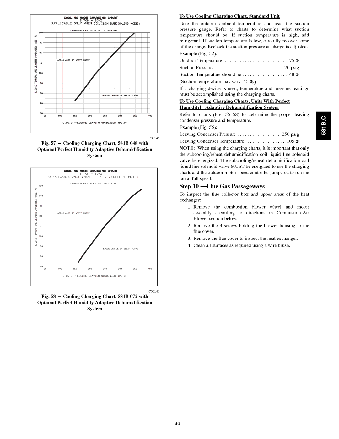
C06145 |
Fig. 57 --- Cooling Charging Chart, 581B 048 with Optional Perfect Humidity Adaptive Dehumidification System
C06146 |
Fig. 58 --- Cooling Charging Chart, 581B 072 with Optional Perfect Humidity Adaptive Dehumidification System
To Use Cooling Charging Chart, Standard Unit
Take the outdoor ambient temperature and read the suction pressure gauge. Refer to charts to determine what suction temperature should be. If suction temperature is high, add refrigerant. If suction temperature is low, carefully recover some of the charge. Recheck the suction pressure as charge is adjusted.
Example (Fig. 52):
Outdoor Temperature . . . . . . . . . . . . . . . . . . . . . . . . . 75°F Suction Pressure . . . . . . . . . . . . . . . . . . . . . . . . . . . 70 psig Suction Temperature should be . . . . . . . . . . . . . . . . . . 48°F (Suction temperature may vary ± 5°F.)
If a charging device is used, temperature and pressure readings must be accomplished using the charging charts.
To Use Cooling Charging Charts, Units With Perfect Humidityt Adaptive Dehumidification System
Refer to charts (Fig.
Example (Fig. 55):
Leaving Condenser Pressure . . . . . . . . . . . . . . . . . 250 psig Leaving Condenser Temperature . . . . . . . . . . . . . . . 105°F
NOTE: When using the charging charts, it is important that only the subcooling/reheat dehumidification coil liquid line solenoid valve be energized. The subcooling/reheat dehumidification coil liquid line solenoid valve MUST be energized to use the charging charts and the outdoor motor speed controller jumpered to run the fan at full speed.
Step 10 —Flue Gas Passageways
To inspect the flue collector box and upper areas of the heat exchanger:
1.Remove the combustion blower wheel and motor assembly according to directions in
2.Remove the 3 screws holding the blower housing to the flue cover.
3.Remove the flue cover to inspect the heat exchanger.
4.Clean all surfaces as required using a wire brush.
581B,C
49