581B,C
|
|
|
|
|
|
|
|
|
|
|
|
|
|
|
|
|
|
|
|
|
| 85 | 90 | 95 | 100 | 105 | 110 | ||
|
|
|
|
|
|
|
|
|
|
|
|
|
|
|
|
|
|
|
|
|
| (29) | (32) | (35) | (38) | (41) | (43) | ||
|
|
|
|
|
|
|
|
|
|
|
|
|
|
|
|
|
|
| 46 |
|
|
|
|
|
|
|
|
|
|
CONTROL | CONTROL POINT |
|
|
|
|
|
|
|
|
|
|
|
|
|
| 4 |
|
|
|
|
|
|
|
|
|
|
|
| |
CURVE APPROX. deg. F (deg. C) |
|
|
|
|
|
|
|
|
|
|
| 4 |
|
|
|
|
|
|
|
|
|
|
|
| |||||
|
|
|
|
|
|
| 42 |
|
|
|
| 80 |
|
|
|
|
|
|
|
| |||||||||
| AT 50% RH |
|
|
|
|
|
|
|
|
|
|
|
|
|
|
|
|
|
|
|
|
|
| ||||||
A | 73 (23) |
|
|
|
|
|
|
|
| AIR |
|
|
|
|
| (27) |
|
|
|
|
|
|
|
| |||||
|
|
|
|
|
|
|
|
|
|
|
|
|
|
|
|
|
|
|
|
|
|
|
| ||||||
|
|
|
|
|
|
|
| 40 |
|
|
|
|
|
|
|
|
|
|
|
|
|
|
|
|
| ||||
B | 70 (21) |
|
|
|
|
|
|
|
|
|
|
|
|
|
|
|
|
|
|
|
|
|
| (%) |
|
| |||
C | 67 (19) |
|
|
|
|
|
|
|
| DRY | 8 |
|
|
|
|
|
|
|
|
|
|
|
|
| HUMIDITY |
|
| ||
D | 63 (17) |
|
|
|
|
|
| POUND |
| 3 |
|
|
|
|
|
|
|
|
|
|
|
|
|
|
|
| |||
|
|
|
|
|
| 36 |
|
|
|
|
|
|
|
|
|
|
|
|
|
|
|
|
| ||||||
|
|
|
|
|
|
|
|
|
|
|
|
|
|
|
| 75 |
|
|
|
|
|
|
|
| |||||
|
|
|
|
|
|
| PER |
|
|
|
|
|
|
|
|
| (24) |
|
|
|
|
|
|
|
| ||||
|
|
|
|
|
|
| 4 |
|
|
|
|
|
|
|
|
|
|
|
|
|
|
|
|
|
|
| |||
|
|
|
|
|
|
| 3 |
|
|
|
|
|
|
|
|
|
|
|
|
|
|
|
|
|
|
| |||
|
|
|
| BTU |
|
|
|
|
|
|
|
|
|
|
|
|
|
|
|
| RELATIVE |
|
|
|
| ||||
|
|
|
| 32 |
|
|
|
|
|
|
|
|
|
|
|
|
|
|
|
|
|
|
|
| |||||
|
|
|
|
|
|
|
|
|
|
|
|
| 70 |
|
|
|
|
|
|
|
|
|
| ||||||
|
|
|
|
| 30 |
|
|
|
|
|
|
|
|
|
|
|
|
|
|
|
|
|
|
|
| ||||
|
|
|
|
|
|
|
|
|
|
|
|
| (21) |
|
|
|
|
|
|
|
|
|
| ||||||
|
|
|
|
|
|
|
|
|
|
|
|
|
|
|
|
|
|
|
|
|
|
|
| ||||||
|
|
| 28 |
|
|
|
|
|
|
|
|
|
|
|
|
|
|
|
|
|
|
|
|
|
|
|
| ||
|
|
|
|
|
|
|
|
|
|
|
|
|
| 0 |
|
|
|
|
|
|
|
|
|
|
|
|
|
| |
| ENTHALPY |
|
|
|
|
|
|
|
|
| 1 | 0 |
| 0 |
|
|
|
|
|
|
|
|
|
|
|
| |||
|
| 26 |
|
|
|
|
|
|
|
|
| 65 |
| 9 | 80 |
|
|
|
|
|
|
|
|
|
|
| |||
|
|
|
|
|
|
|
|
|
|
|
|
|
|
|
|
|
|
|
|
|
|
|
| ||||||
|
|
|
|
|
|
|
|
|
|
|
|
|
|
|
|
|
|
|
|
|
|
|
|
|
| ||||
| 4 |
|
|
|
|
|
|
|
|
|
| (18) |
|
|
|
|
| 70 |
|
|
|
|
|
|
|
|
|
| |
|
|
|
|
|
|
|
|
|
|
|
|
|
|
|
|
|
|
|
|
|
|
|
|
|
|
| |||
|
|
|
|
|
|
|
|
|
|
|
|
|
|
|
|
|
|
|
|
|
|
|
|
|
|
|
| ||
| 2 |
|
|
|
|
|
|
|
|
|
|
|
|
|
|
|
|
|
| 0 |
|
|
|
|
|
|
|
| |
| 2 |
|
|
|
|
|
|
|
|
|
|
|
|
|
|
|
|
|
| 6 |
|
|
|
|
|
|
|
| |
|
|
|
|
|
|
|
|
|
|
|
|
|
|
|
|
|
|
|
|
|
|
|
|
|
|
|
| ||
| 2 |
|
|
|
|
|
|
|
| 60 |
|
|
|
|
|
|
|
|
|
| 50 |
|
|
|
|
|
|
|
|
|
|
|
|
|
|
|
|
|
|
|
|
|
|
|
|
|
|
|
|
|
|
|
|
|
|
|
| ||
| 0 |
|
|
|
|
|
|
|
| (16) |
|
|
|
|
|
|
|
|
|
|
|
|
|
|
|
|
| ||
| 2 |
|
|
|
|
|
|
|
|
| A |
|
|
|
|
|
|
|
|
| 4 | 0 |
|
|
|
|
|
| |
8 |
|
|
|
|
|
|
| 55 |
|
|
|
|
|
|
|
|
|
|
|
|
|
|
|
|
| ||||
|
|
|
|
|
|
|
|
|
|
|
|
|
|
|
|
|
|
|
|
|
|
|
|
|
|
| |||
|
|
|
|
|
|
|
|
|
|
|
|
|
|
|
|
|
|
|
|
|
|
|
|
|
|
|
| ||
1 |
|
|
|
|
|
|
| (13) |
| B |
|
|
|
|
|
|
|
|
|
|
|
|
| 30 |
|
|
|
|
|
6 |
|
|
|
|
|
|
|
|
|
|
|
|
|
|
|
|
|
|
|
|
|
|
|
|
|
| |||
1 |
|
|
|
|
|
| 50 |
|
|
|
|
|
|
|
|
|
|
|
|
|
|
|
|
|
|
|
|
|
|
4 |
|
|
|
|
|
| C |
|
|
|
|
|
|
|
|
|
|
|
|
|
|
|
|
|
|
|
|
| |
|
|
|
|
| (10) |
|
|
|
|
|
|
|
|
|
|
|
|
|
|
|
|
|
|
|
|
| |||
1 |
|
|
|
|
|
|
|
|
|
|
|
|
|
|
|
|
|
|
|
|
|
|
| 20 |
|
|
| ||
|
|
|
|
|
|
|
|
|
|
|
|
|
|
|
|
|
|
|
|
|
|
|
|
|
|
|
|
| |
2 |
|
| 45 |
|
| D |
|
|
|
|
|
|
|
|
|
|
|
|
|
|
|
|
|
|
|
|
|
| |
1 |
|
| (7) |
|
|
|
|
|
|
|
|
|
|
|
|
|
|
|
|
|
|
|
|
|
|
|
| ||
|
| 40 |
|
|
|
|
|
|
|
|
|
|
|
|
|
|
|
|
|
|
|
|
|
|
|
|
| ||
|
|
|
|
|
|
|
|
|
|
|
|
|
|
|
|
|
|
|
|
|
|
|
|
|
|
|
| 0 | |
|
| (4) |
|
|
|
|
|
|
|
|
|
|
|
|
|
|
|
|
|
|
|
|
|
|
|
|
|
| |
|
|
|
|
|
|
|
|
|
|
|
|
|
|
|
|
|
|
|
|
|
|
|
|
|
|
|
| 1 | |
| 35 |
|
|
|
|
|
|
|
|
|
|
|
|
|
|
|
|
|
|
|
|
|
|
|
|
|
|
|
|
| (2) |
|
|
|
|
|
|
|
|
|
|
|
|
|
|
|
|
|
|
|
|
|
|
|
|
|
|
|
|
|
|
|
|
|
|
|
|
|
|
|
|
|
|
|
|
|
|
| D C |
| B | A |
|
|
|
|
|
|
|
|
|
|
|
|
|
|
|
|
|
|
|
|
|
|
|
|
|
|
|
|
|
|
|
|
|
|
| HIGH LIMIT | |
|
|
|
|
|
|
|
|
|
|
|
|
|
|
|
|
|
|
|
|
|
|
|
|
|
|
|
|
| |
|
|
|
|
|
|
|
|
|
|
|
|
|
|
|
|
|
|
|
|
|
|
|
|
|
|
|
|
| CURVE |
| 35 | 40 | 45 |
|
| 50 | 55 |
| 60 | 65 |
|
|
| 70 |
| 75 |
| 80 | 85 | 90 | 95 | 100 | 105 | 110 | |||||
| (2) | (4) | (7) |
|
| (10) | (13) | (16) | (18) |
|
| (21) |
| (24) |
| (27) | (29) | (32) | (35) | (38) | (41) | (43) | |||||||
| APPROXIMATE DRY BULB |
|
|
| |||||||||||||||||||||||||
C06037
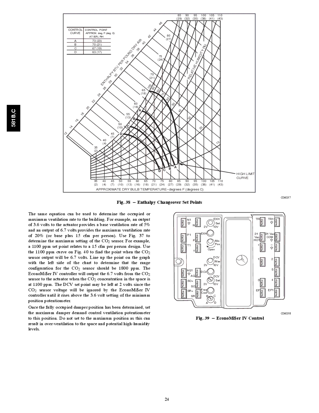
Fig. 38 --- Enthalpy Changeover Set Points
The same equation can be used to determine the occupied or |
|
|
|
|
| |||
maximum ventilation rate to the building. For example, an output | N1 |
| EXH | TR | TR1 | |||
of 3.6 volts to the actuator provides a base ventilation rate of 5% | N |
| Set |
|
| |||
2V | 10V |
|
| |||||
and an output of 6.7 volts provides the maximum ventilation rate |
|
|
| |||||
| EXH |
| 24 | 24 Vac | ||||
of 20% (or base plus 15 | cfm per person). Use | Fig. 37 to | P1 |
| ||||
|
| Vac | COM | |||||
determine the maximum setting of the CO2 sensor. For example, | P |
| Min | HOT | _ | |||
a 1100 ppm set point relates to a 15 cfm per person design. Use | T1 |
| Pos | + | ||||
|
| |||||||
| Open |
|
| |||||
the 1100 ppm curve on Fig. 40 to find the point when the CO2 | T |
|
| |||||
|
|
|
| |||||
|
|
|
|
|
|
|
| |
sensor output will be 6.7 volts. Line up the point on the graph |
|
| DCV | 1 | 2 | |||
with the left side of | the | chart to determine that | the range |
|
| Max | ||
|
|
|
| |||||
| 2V | 10V |
|
| ||||
configuration for the | CO2 | sensor should be 1800 | ppm. The |
|
|
| ||
AQ1 | DCV |
|
| 5 | ||||
EconoMi$er IV controller will output the 6.7 volts from the CO2 |
|
|
| |||||
|
|
|
| |||||
AQ |
| DCV |
|
| ||||
sensor to the actuator when the CO2 concentration in the space is |
|
| 4 | |||||
SO+ |
| Set | 3 | |||||
at 1100 ppm. The DCV set point may be left at 2 volts since the | SO | 2V | 10V |
|
| |||
CO2 sensor voltage will be ignored by the EconoMi$er IV |
|
| EF | EF1 | ||||
SR+ | Free |
| ||||||
controller until it rises above the 3.6 volt setting of the minimum |
| Cool |
|
|
| |||
SR | B | C |
|
| ||||
position potentiometer. |
|
|
|
| A | D |
|
|
Once the fully occupied damper position has been determined, set |
|
|
| |||||
|
|
|
|
| ||||
the maximum damper demand control ventilation potentiometer |
| Fig. 39 | C06038 | |||||
to this position. Do not set to the maximum position as this can |
|
| ||||||
result in
24