(Text continued from page 13)

CAUTION: Unstable operation may occur when the gas valve and manifold assembly are forced out of po- sition while connecting improperly-routed rigid gas pip- ing to the gas valve. Use a backup wrench when mak- ing connection to avoid strain on, or distortion of, the gas control piping.

CAUTION: If a ¯exible conductor is required or al- lowed by the authority having jurisdiction, black iron pipe shall be installed at the gas valve and shall ex- tend a minimum of 2 in. outside the unit casing.

WARNING: Never use a match or other open ¯ame when checking for gas leaks. Never purge gas line into combustion chamber. Failure to follow this warning could result in an explosion causing personal injury or death.

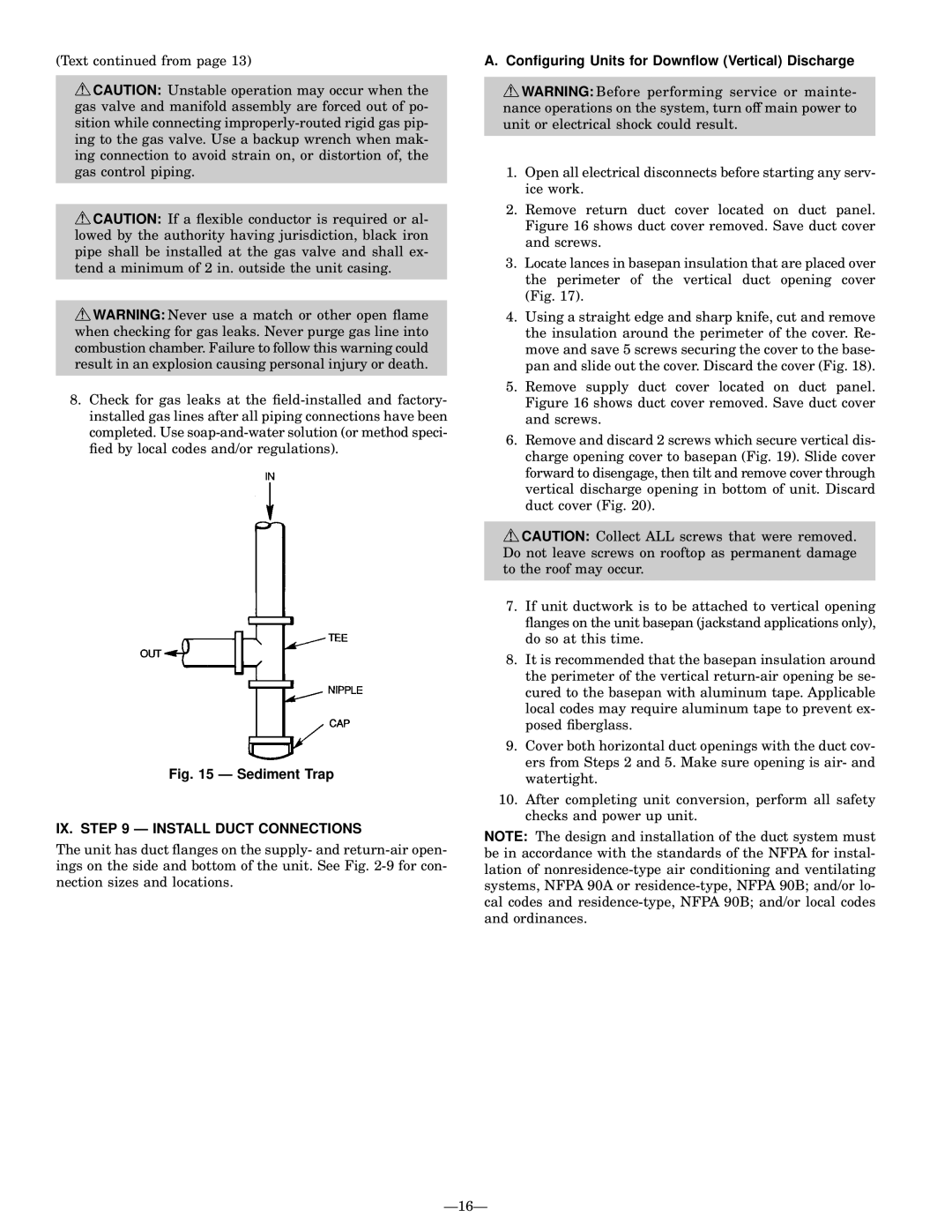
8.Check for gas leaks at the ®eld-installed and factory- installed gas lines after all piping connections have been completed. Use soap-and-water solution (or method speci- ®ed by local codes and/or regulations).

Fig. 15 Ð Sediment Trap

IX. STEP 9 Ð INSTALL DUCT CONNECTIONS

The unit has duct ¯anges on the supply- and return-air open- ings on the side and bottom of the unit. See Fig. 2-9 for con- nection sizes and locations.

A. Con®guring Units for Down¯ow (Vertical) Discharge

WARNING: Before performing service or mainte- nance operations on the system, turn off main power to unit or electrical shock could result.

1.Open all electrical disconnects before starting any serv- ice work.

2.Remove return duct cover located on duct panel. Figure 16 shows duct cover removed. Save duct cover and screws.

3.Locate lances in basepan insulation that are placed over the perimeter of the vertical duct opening cover (Fig. 17).

4.Using a straight edge and sharp knife, cut and remove the insulation around the perimeter of the cover. Re- move and save 5 screws securing the cover to the base- pan and slide out the cover. Discard the cover (Fig. 18).

5.Remove supply duct cover located on duct panel. Figure 16 shows duct cover removed. Save duct cover and screws.

6.Remove and discard 2 screws which secure vertical dis- charge opening cover to basepan (Fig. 19). Slide cover forward to disengage, then tilt and remove cover through vertical discharge opening in bottom of unit. Discard duct cover (Fig. 20).

CAUTION: Collect ALL screws that were removed. Do not leave screws on rooftop as permanent damage to the roof may occur.

7.If unit ductwork is to be attached to vertical opening ¯anges on the unit basepan (jackstand applications only), do so at this time.

8.It is recommended that the basepan insulation around the perimeter of the vertical return-air opening be se- cured to the basepan with aluminum tape. Applicable local codes may require aluminum tape to prevent ex- posed ®berglass.

9.Cover both horizontal duct openings with the duct cov- ers from Steps 2 and 5. Make sure opening is air- and watertight.

10.After completing unit conversion, perform all safety checks and power up unit.

NOTE: The design and installation of the duct system must be in accordance with the standards of the NFPA for instal- lation of nonresidence-type air conditioning and ventilating systems, NFPA 90A or residence-type, NFPA 90B; and/or lo- cal codes and residence-type, NFPA 90B; and/or local codes and ordinances.

Ð16Ð

Page 16
Image 16
Bryant 588A, 589A user manual IX. Ð Install Duct Connections, Conguring Units for Down¯ow Vertical Discharge

589A, 588A specifications

The Bryant 588A is a high-efficiency gas furnace celebrated for its advanced technology and superior performance in residential heating. Known for its reliability and durable construction, this model is ideal for homeowners looking for warmth and comfort during colder months.

One of the standout features of the Bryant 588A is its remarkable AFUE (Annual Fuel Utilization Efficiency) rating, which can reach up to 96.5%. This high efficiency means that a significant portion of the fuel consumed is converted into usable heat, leading to lower energy bills and a reduced carbon footprint. The furnace utilizes a two-stage heating system, which improves comfort levels by providing more consistent temperatures and reducing the frequency of temperature swings in the home.

Another notable characteristic is the incorporation of a multi-speed blower motor. This innovation enhances airflow and optimizes energy use by adjusting the fan speed according to the heating needs of the home. The variable speed operation also helps to minimize noise levels, creating a quieter environment compared to traditional single-speed furnaces.

The Bryant 588A features an advanced control system that allows for better system management and can be integrated with smart home technologies. This allows homeowners to monitor and adjust their heating settings remotely, offering convenience and efficiency. Additionally, the furnace is compatible with Bryant’s Evolution System, which provides advanced diagnostic features and improved energy performance.

Durability is a key characteristic of the Bryant 588A, as it is constructed with a heavy-duty cabinet designed to withstand the rigors of daily use and harsh weather conditions. The unit also includes a corrosion-resistant heat exchanger, ensuring longevity and reliability.

Furthermore, the Bryant 588A operates quietly, thanks to its insulated cabinet and advanced design. This feature is especially appreciated by homeowners seeking a peaceful living environment free from disruptive noises typically associated with heating systems.

In summary, the Bryant 588A gas furnace combines high efficiency, innovative technology, and durable construction. Its effective heating capabilities paired with user-friendly features make it a smart investment for anyone looking to enhance their home heating system while enjoying lower energy costs and increased comfort.