I. AIR FILTER

CAUTION: Never operate the unit without a suit- able air ®lter in the return-air duct system. Always re- place the ®lter with the same dimensional size and type as originally installed. See Tables 1 and 2 for recom- mended ®lter sizes.

Inspect air ®lter(s) at least once each month and replace (throwaway-type) or clean (cleanable-type) at least twice dur- ing each heating and cooling season or whenever the ®lter(s) becomes clogged with dust and lint.

II. UNIT TOP REMOVAL

NOTE: When performing maintenance or service procedures that require removal of the unit top, be sure to perform all of the routine maintenance procedures that require top re- moval, including: inspection of the heat exchanger area, coil inspection and cleaning, and condensate drain pan inspec- tion and cleaning.

Only quali®ed service personnel should perform mainte- nance and service procedures that require unit top removal. Refer to the following top removal procedures:

1.Turn off gas supply, then turn off electric power to unit.

2.Remove all screws that secure unit top, including screws around 4 sides and those on top that screw into internal divider panels. Save all screws.

3.Lift top from unit carefully. Set top on edge.

4.Carefully replace and secure unit top to unit, using screws removed in Step 2, when maintenance and/or service pro- cedures are completed. (Be sure to use original screws that have rubber washers to seal out water when secur- ing top to internal divider panels.)

III.EVAPORATOR BLOWER AND MOTOR

NOTE: Motors without oilers are prelubricated. Do not at- tempt to lubricate these motors.

For longer life, operating economy, and continuing efficiency, clean accumulated dirt and grease from the blower wheel and motor annually.

Lubricate the motor every 5 years if the motor is used inter- mittently (thermostat FAN switch in AUTO. position), or ev- ery 2 years if the motor is used continuously (thermostat FAN switch in ON position).

WARNING: Turn off the gas supply, then disconnect and tag electrical power to the unit before cleaning and lubricating the blower motor and wheel. Failure to ad- here to this warning could cause personal injury or death.

To clean and lubricate the blower motor and wheel:

1.Remove and disassemble blower assembly as follows:

a.Remove blower access door.

b.On standard non-ICM units disconnect motor lead from blower relay (BR). Disconnect yellow lead from ter- minal L2 of the contactor.

c.On all units remove blower assembly from unit. Re- move screws securing blower to gas partition and slide assembly out. Be careful not to tear insulation in blower compartment.

d.Ensure proper reassembly by marking blower wheel and motor in relation to blower housing before dis- assembly.

e.Loosen setscrew(s) that secures wheel to motor shaft, remove screws that secure motor mount brackets to

housing, and slide motor and motor mount out of housing.

2.Lubricate motor as follows:

a.Thoroughly clean all accumulations of dirt or grease from motor housing.

b.Remove dust caps or plugs from oil ports located at each end of motor.

c.Use a good grade of SAE 20 nondetergent motor oil and put one teaspoon (3¤16 oz. or 16 to 25 drops) in each oil port.

d.Allow time for oil to be absorbed by each bearing, then wipe excess oil from motor housing.

e.Replace dust caps or plugs in oil ports.

3.Remove and clean blower wheel as follows:

a.Ensure proper reassembly by marking wheel orientation.

b.Lift wheel from housing. When handling and/or clean- ing blower wheel, be sure not to disturb balance weights (clips) on blower wheel vanes.

c.Remove caked-on dirt from wheel and housing with a brush. Remove lint and/or dirt accumulations from wheel and housing with vacuum cleaner, using soft brush attachment. Remove grease and oil with mild solvent.

d.Reassemble wheel into housing.

e.Reassemble motor into housing. Be sure setscrews are tightened on motor shaft ¯ats and not on round part of shaft.

f.Reinstall blower access door.

4.Restore electrical power, then gas supply to unit. Start unit and check for proper blower rotation and motor speeds during heating and cooling cycles.

IV. FLUE GAS PASSAGEWAYS

To inspect the ¯ue collector box and upper areas of the heat exchanger:

1.Remove the combustion blower wheel and motor assem- bly according to directions in Combustion-Air Blower sec- tion on page 46.

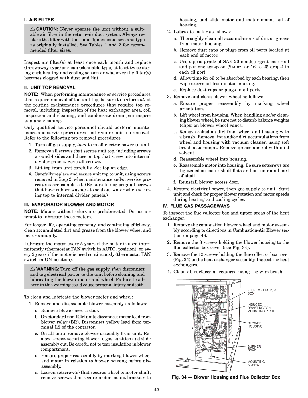
2.Remove the 3 screws holding the blower housing to the ¯ue collector box cover (see Fig. 34).

3.Remove the 12 screws holding the ¯ue collector box cover (Fig. 34) to the heat exchanger assembly. Inspect the heat exchangers.

4.Clean all surfaces as required using the wire brush.

FLUE COLLECTOR

BOX

INDUCED

DRAFT MOTOR

MOUNTING PLATE

BLOWER

HOUSING

BURNER

RACK

MOUNTING

SCREW

Fig. 34 Ð Blower Housing and Flue Collector Box

Ð45Ð

Page 45
Image 45
Bryant 589A, 588A AIR Filter, II. Unit TOP Removal, III. Evaporator Blower and Motor, IV. Flue GAS Passageways, Ð45Ð

589A, 588A specifications

The Bryant 588A is a high-efficiency gas furnace celebrated for its advanced technology and superior performance in residential heating. Known for its reliability and durable construction, this model is ideal for homeowners looking for warmth and comfort during colder months.

One of the standout features of the Bryant 588A is its remarkable AFUE (Annual Fuel Utilization Efficiency) rating, which can reach up to 96.5%. This high efficiency means that a significant portion of the fuel consumed is converted into usable heat, leading to lower energy bills and a reduced carbon footprint. The furnace utilizes a two-stage heating system, which improves comfort levels by providing more consistent temperatures and reducing the frequency of temperature swings in the home.

Another notable characteristic is the incorporation of a multi-speed blower motor. This innovation enhances airflow and optimizes energy use by adjusting the fan speed according to the heating needs of the home. The variable speed operation also helps to minimize noise levels, creating a quieter environment compared to traditional single-speed furnaces.

The Bryant 588A features an advanced control system that allows for better system management and can be integrated with smart home technologies. This allows homeowners to monitor and adjust their heating settings remotely, offering convenience and efficiency. Additionally, the furnace is compatible with Bryant’s Evolution System, which provides advanced diagnostic features and improved energy performance.

Durability is a key characteristic of the Bryant 588A, as it is constructed with a heavy-duty cabinet designed to withstand the rigors of daily use and harsh weather conditions. The unit also includes a corrosion-resistant heat exchanger, ensuring longevity and reliability.

Furthermore, the Bryant 588A operates quietly, thanks to its insulated cabinet and advanced design. This feature is especially appreciated by homeowners seeking a peaceful living environment free from disruptive noises typically associated with heating systems.

In summary, the Bryant 588A gas furnace combines high efficiency, innovative technology, and durable construction. Its effective heating capabilities paired with user-friendly features make it a smart investment for anyone looking to enhance their home heating system while enjoying lower energy costs and increased comfort.