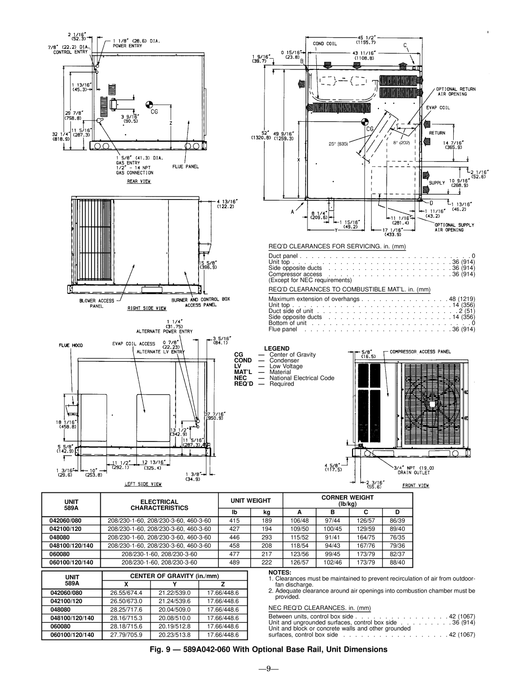
589A, 588A specifications
The Bryant 588A is a high-efficiency gas furnace celebrated for its advanced technology and superior performance in residential heating. Known for its reliability and durable construction, this model is ideal for homeowners looking for warmth and comfort during colder months.One of the standout features of the Bryant 588A is its remarkable AFUE (Annual Fuel Utilization Efficiency) rating, which can reach up to 96.5%. This high efficiency means that a significant portion of the fuel consumed is converted into usable heat, leading to lower energy bills and a reduced carbon footprint. The furnace utilizes a two-stage heating system, which improves comfort levels by providing more consistent temperatures and reducing the frequency of temperature swings in the home.
Another notable characteristic is the incorporation of a multi-speed blower motor. This innovation enhances airflow and optimizes energy use by adjusting the fan speed according to the heating needs of the home. The variable speed operation also helps to minimize noise levels, creating a quieter environment compared to traditional single-speed furnaces.
The Bryant 588A features an advanced control system that allows for better system management and can be integrated with smart home technologies. This allows homeowners to monitor and adjust their heating settings remotely, offering convenience and efficiency. Additionally, the furnace is compatible with Bryant’s Evolution System, which provides advanced diagnostic features and improved energy performance.
Durability is a key characteristic of the Bryant 588A, as it is constructed with a heavy-duty cabinet designed to withstand the rigors of daily use and harsh weather conditions. The unit also includes a corrosion-resistant heat exchanger, ensuring longevity and reliability.
Furthermore, the Bryant 588A operates quietly, thanks to its insulated cabinet and advanced design. This feature is especially appreciated by homeowners seeking a peaceful living environment free from disruptive noises typically associated with heating systems.
In summary, the Bryant 588A gas furnace combines high efficiency, innovative technology, and durable construction. Its effective heating capabilities paired with user-friendly features make it a smart investment for anyone looking to enhance their home heating system while enjoying lower energy costs and increased comfort.

